7-2 Adapter Installation Waveguide Adapter Kit Instructions
7-4 PN: 10410-00311 Rev. F VectorStar ME7838x/x4 Modules RM
1. Remove Waveguide to W Coax Adapter (Item 8) from the kit.
2. Carefully connect the coax end of the Waveguide to Coax Adapter (Item 8) into the W connector of the
3744x mmW Module (Item 11).
3. Use Torque Wrench, (Item 15) - 0.45 N· m (4 lbf· in) to tighten the W connection between the 3744x mmW
Module and Waveguide to Coax Adapter.
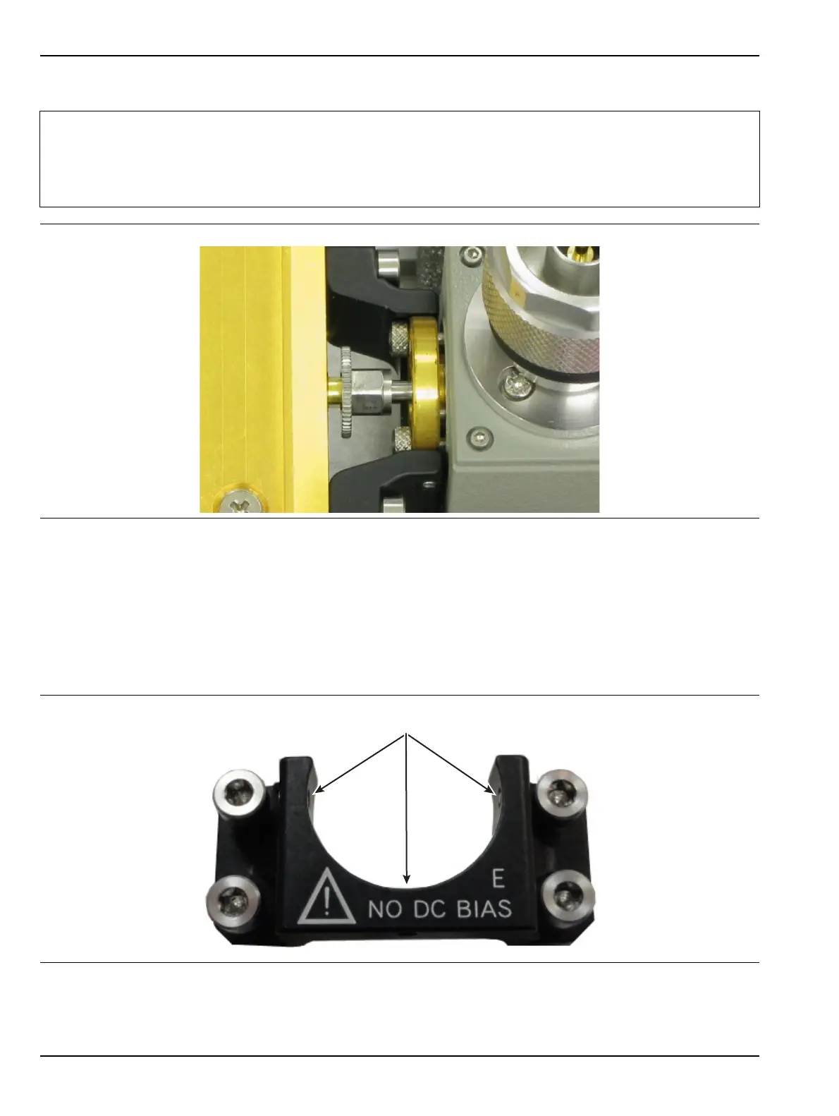
4. Inspect the Adapter Mounting Bracket (Item 9).
Ensure the three set screws (Item 4) do not protrude out into the semicircular area.
Note
If there isn’t access for waveguide flange mounting screws on the DUT, the Waveguide flange socket
head screws (Item 5) must be installed from the back side of the Waveguide to Coax Adapter
(Item 8) before proceeding to install the adapter to the 3744x mm Module (Item 11) (see Figure 7-4).
Only the flange mounting screws (Item 5) with the small metric head will work. Special Metric Hex
Wrench (Item 3) is used to tighten the flange screws in the limited space.
Figure 7-4. Installing WG Flange with Limited DUT Space
Figure 7-5. Adapter Mounting Bracket Set Screws
Ensure set screws do not protrude into semicircle