8-7 3744x-Rx Module Outline Mounting in User-Supplied Bracket
8-6 PN: 10410-00311 Rev. F VectorStar ME7838x/x4 Modules RM
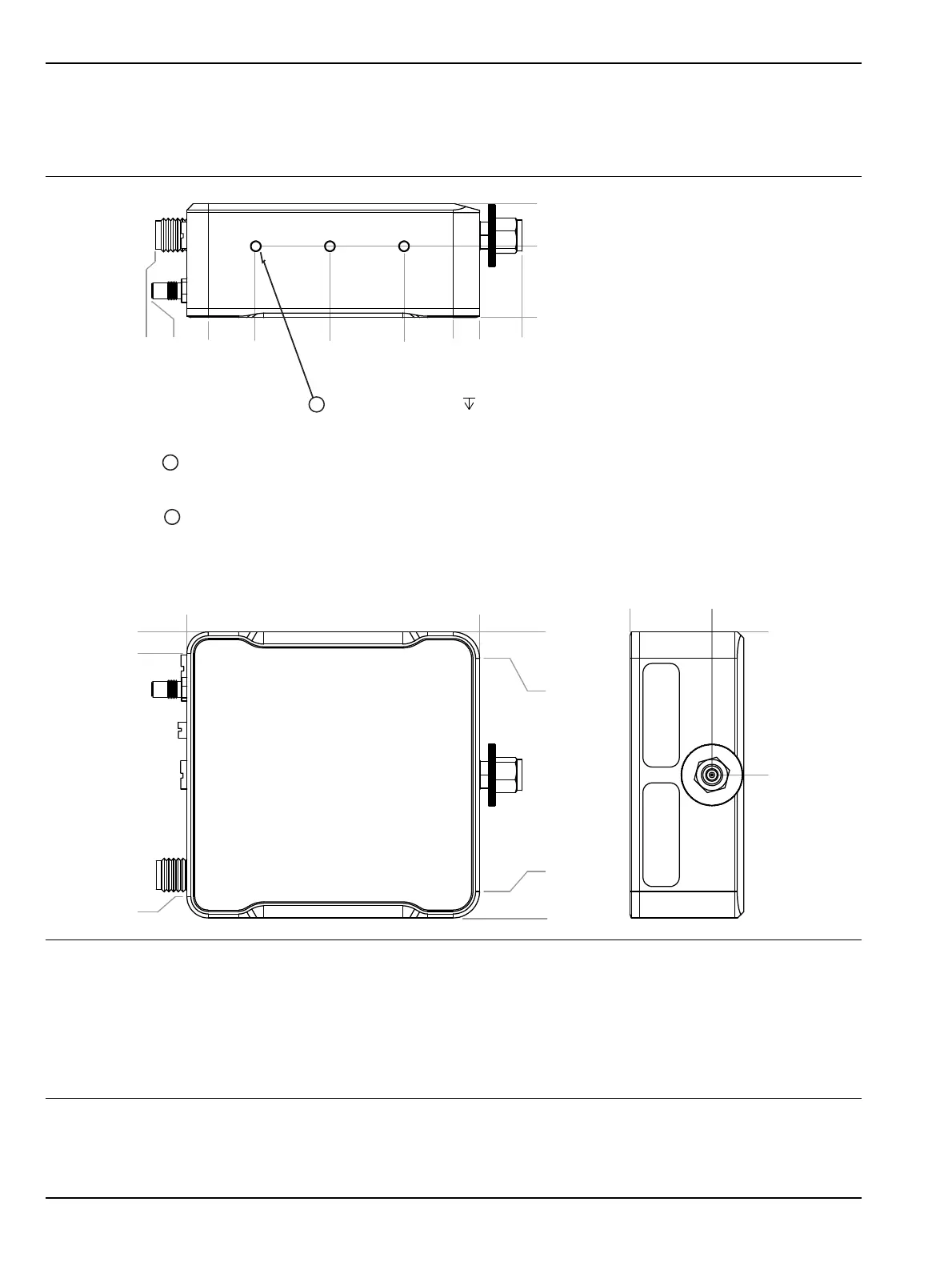
8-7 3744x-Rx Module Outline
Figure 8-5 shows the outline mechanical requirements for the 3743A-Rx and 3744E-Rx Millimeter-Wave
Modules.
All dimensions in millimeters.
1 – For mounting, use M2 screws sufficient length that use the maximum number of module housing threads.
A thread engagement of 5 to 6 mm is recommended.
Do not bottom out fasteners.
2 – The module housing is copper. Do not over-torque screws.
3 – The threaded module mounting holes are M2 tapped x 8.6 mm deep, three each side, six total.
Figure 8-5. 3744x-Rx Millimeter-Wave Module Outline Drawing
0
5.0
49.0
54.00
0
4.0
50.0
0
55.3
0
27.0
0
15.5
0
13.47
21.51
0
8.0
5.0
14.26
28.26
42.26
51.3
61.9
60.9
Use M2 screws of sucient length for mounting that use the recommended
number of threads in the module housing. The recommended thread engagement
is 5 to 6 mm. Do not bottom out fastners.
The module housing material is copper. Do not over torque fasteners.
1
2
M2 TAPPED HOLES
8.6
3 EACH SIDE
3