8-3 MA25400A Module Outline Mounting in User-Supplied Bracket
8-2 PN: 10410-00311 Rev. F VectorStar ME7838x/x4 Modules RM
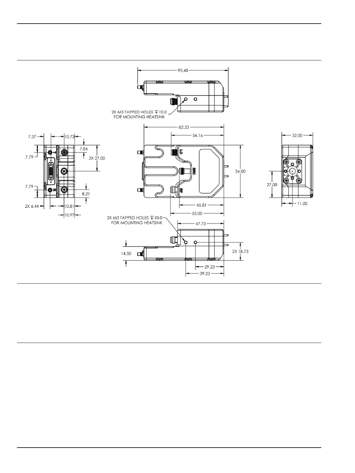
8-3 MA25400A Module Outline
Figure 8-2 shows the outline mechanical requirements for the MA25400A Millimeter-Wave Module.
All dimensions in millimeters.
1 – For mounting, use M3 screws sufficient length that use the maximum number of module housing threads.
A thread engagement of 5 to 6 mm is recommended.
Do not bottom out fasteners.
2 – The module housing is copper. Do not over-torque screws.
3 – The threaded module mounting holes are M3 tapped x 10 mm deep, two each side, four total.
Figure 8-1. MA25400A Millimeter-Wave Module Outline Drawing