Symbols and Indicators
Spectrum Master UG PN: 10580-00277 Rev. E 2-15
RF In
50 Ω Type-N connector (MS2722C, MS2723C, MS2724C) or a 50 Ω Type-K male ruggedized
connector (MS2725C, MS2726C).
To prevent damage to your instrument, do not use pliers or a plain wrench to tighten the
Type-N connector. Do not overtighten the connector. The recommended torque is 12 lbf·in to
15 lbf·in (1.36 N·m to 1.70 N·m).
GPS Antenna Connector (Option 31)
The GPS antenna connection on the Spectrum Master is type SMA(F). Selectable +3 VDC or
+5 VDC antenna power.
To prevent damage to your instrument, do not use pliers or a plain wrench to tighten the
SMA connector. Do not overtighten the connector. The recommended torque is 8 lbf·in
(0.9 N·m or 90 N·cm).
2-12 Symbols and Indicators
The following symbols and indicators convey the instrument status or condition on the
display.
Cal Status On:
The Spectrum Master has been calibrated with discrete Open, Short, and Load components.
Cal Status Off:
The Spectrum Master has not been calibrated.
Battery Symbol:
The battery symbol above the display indicates the charge remaining in the battery.
The colored section inside the symbol changes size and color with the charge level.
Green: Battery is 30% to 100% charged
Yellow: Battery is 10% to 30% charged
Red: Battery 0% to 10% charged
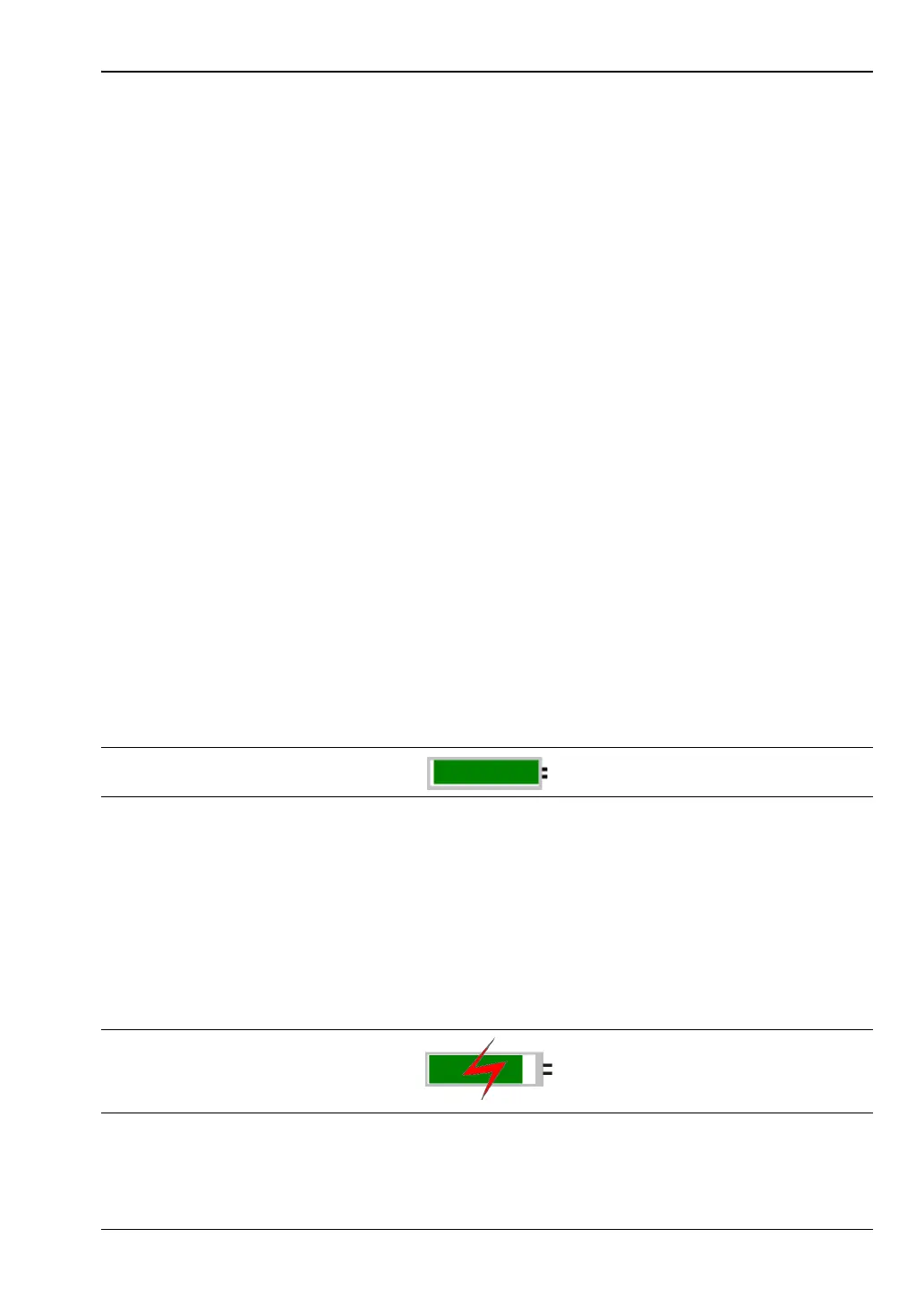
Lightning Bolt: Battery is being charged (any color symbol)
When the battery is charging, either from the AC-DC Adapter or the 12 Volt DC adapter, the
symbol changes to that shown in Figure 2-12:
Figure 2-11. Battery Status
Figure 2-12. Battery Charging Status