Technical Documentation ECE10CM, DC10CM Page 17 of 39
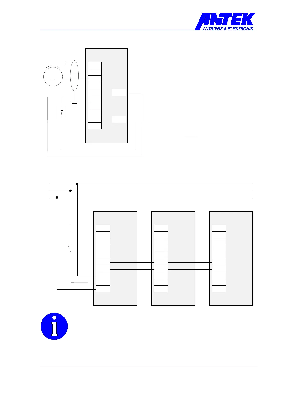
Permanently Excited DC Motor
♦ Min. cable cross-section 1.5 mm²
♦ Connect motor cable to plug-in terminals
PE, W, V
(Starting torque: 0.5 - 0.6 Nm).
Clockwise rotation for polarity illustrated.
♦ Insert screen correctly in accordance with
EMC For feedback system and sensor
wire connections see Chapter 4.4.8
♦ Monitoring the motor temperature by
means of a thermal protection contact is
recommended.
If no thermal protection contact is used,
input X5-2 must be bridged to
HIGH potential e.g. +15V X6-3.
4.4.3 Interconnected Operation of Several
Drive Controls
L
-
R
B
L
1
L
+
P
E
X
2
N
L
-
R
B
L
1
L
+
P
E
X
2
L
-
R
B
L
1
L
+
P
E
X
2
drive control
drive control
drive control
The total connected load may not exceed 1.4 kVA in interconnected
operation, otherwise
♦ every drive control must be supplied with mains power. Nevertheless,
an energy exchange can take place on the intermediate circuit.
♦ or a separate supply module must be used.
W
P
E
L
-
R
B
L
1
N
L
+
P
E
X
2
D
C
1
0
C
M
M
6
-
3
X
5
-
2
U
-
+
drive control
 Loading...