Technical Documentation ECE10CM, DC10CM Page 21 of 39
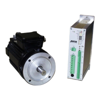
4.4.6 Signalling Outputs
X
5
2
1
6
5
4
9
8
7
1
1
1
2
+
R
E
D
Y
+
R
E
D
Y
-
n
-
R
E
F
-
+
-
drive control
machine control
internal circuit
10nk
switching voltage max. 35 VDC
UCE
SAT
<1V at 10mA
READY (X5-8/9) Transmitting when ready.
Display by „READY“LED on front panel.
The following faults are displayed:
(See Displays Chapter )
Each display corresponds to an LED on the front panel
A fault is stored until it has been reset.
For resetting of fault display see Chapter Ω
n-REF (X5-10/11) Nominal / Actual Function
Transmitting, if the speed regulator does not show any deviation. The
signal has a time delay in order to suppress dynamic control
deviations during acceleration or braking.
n < REF Function
Transmitting, if the actual speed is < 2% of the maximum speed
(For LED display see 5.1; for setting see 5.4)
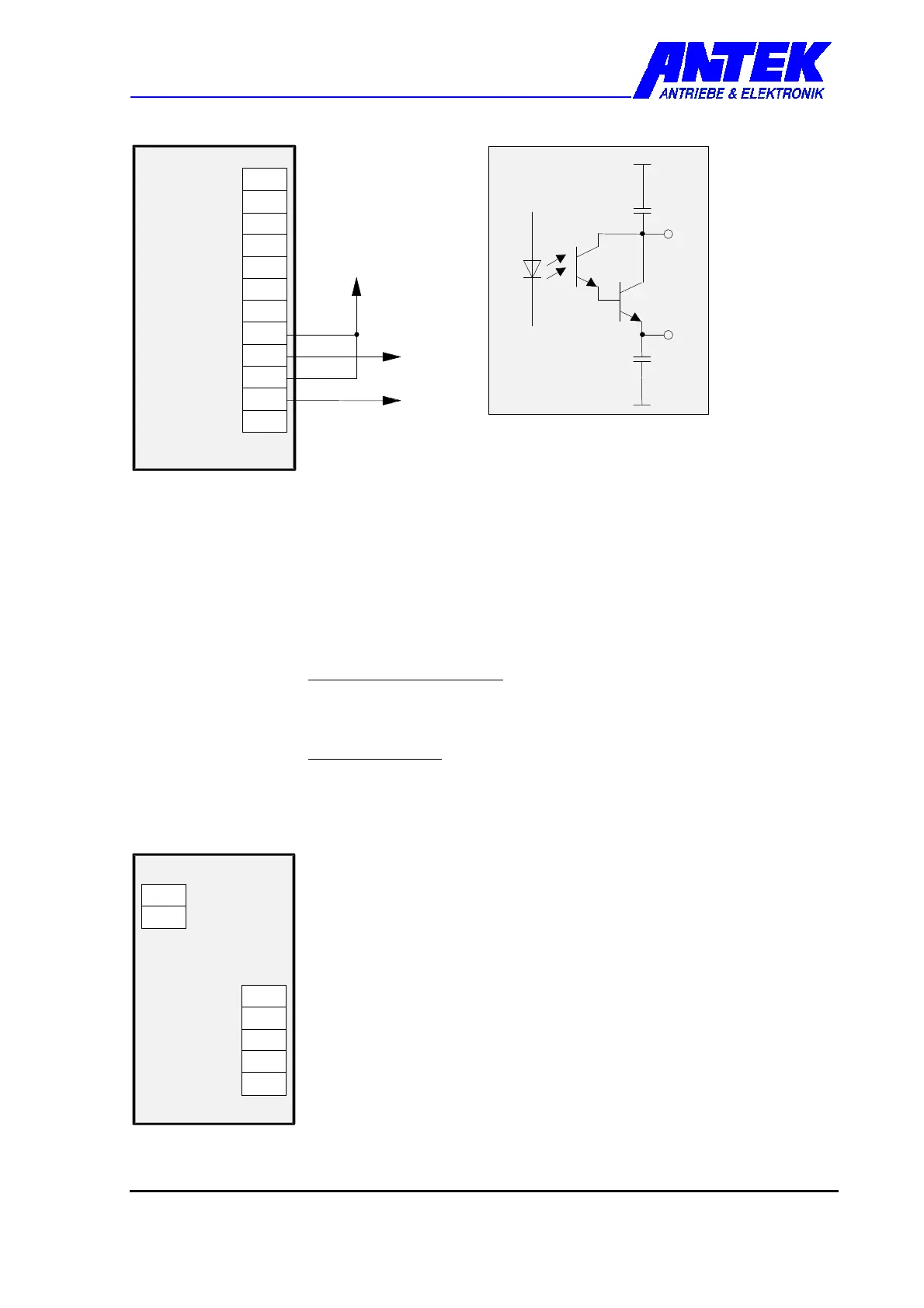
4.4.7 Auxiliary Voltages
+24V (X1-1) Fan supply voltage
GND (X1-2) Max. load 100 mA
+10V (X6-1) Auxiliary voltages
-10V (X6-2) Max. total load 1.5 W
+15V (X6-3)
-15V (X6-4)
GND (X6-5)
X
6
4
+
1
5
-
1
5
5
G
N
D
1
+
2
4
X
1
drive control
 Loading...