Page 20 of 39 Technical Documentation ECE10CM, DC10CM
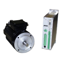
4.4.5.2 Analogue Signal Connection
X
5
3
1
5
4
8
7
1
0
1
1
n
-
S
E
T
+
I
-
L
I
M
I
T
G
N
D
-
1
0
5
1
0
0
k
+
1
0
2
1
3
1
2
5
10nk
6
1
0
0
k
-
+
7
1
0
k
-
+
1
0
0
k
drive control
speed
current limit
10nk
10nk
I-max
internal circuit
µ1k
12V
100k
µ1k
Analogue set point cables should
be screened in general!
n-SET+ (X5-5) Differential input to manual speed set point default
n-SET - (X5-6) Tip: With unipolar signals connect " n-SET -" input to GND.
Input voltage: -10 VDC ... +10 VDC
Input resistance: Ri = 100 kΩ
Reference potential: GND
Positive differential input voltage produces
♦ a clockwise rotating field with ECE motors (See Chapter 4.4.8.1)
♦ a positive motor voltage with DC motors
I-LIMIT (X5-7) Input to external current limiting default
Input voltage: 0 ... +10 VDC
Input resistance: Ri = 10 kΩ
Reference potential: GND
0VDC = 0%
10VDC = 100% of internally set peak current
If this function is not required, this input must be connected to
≥
10VDC e.g. X6-1.
 Loading...