Technical Documentation ECE10CM, DC10CM Page 31 of 39
5.4 Encoding
R
E
A
D
Y
<
U
>
E
N
A
B
L
E
L
I
M
I
T
T
E
M
P
S
-
F
A
I
L
n
-
R
E
F
D
I
R
n
-
S
E
T
G
N
D
I
-
m
a
x
I
-
A
C
T
I
-
S
E
T
n
-
A
C
T
O
F
F
S
E
T
n
-
m
a
x
I
-
m
a
x
I
x
R
T
r
V
p
T
n
X
2
2
4
V
X
3
G
N
D
V
W
P
E
L
-
R
B
U
L
1
N
L
+
P
E
X
1
X
4
X
5
X
6
F
1
R
B
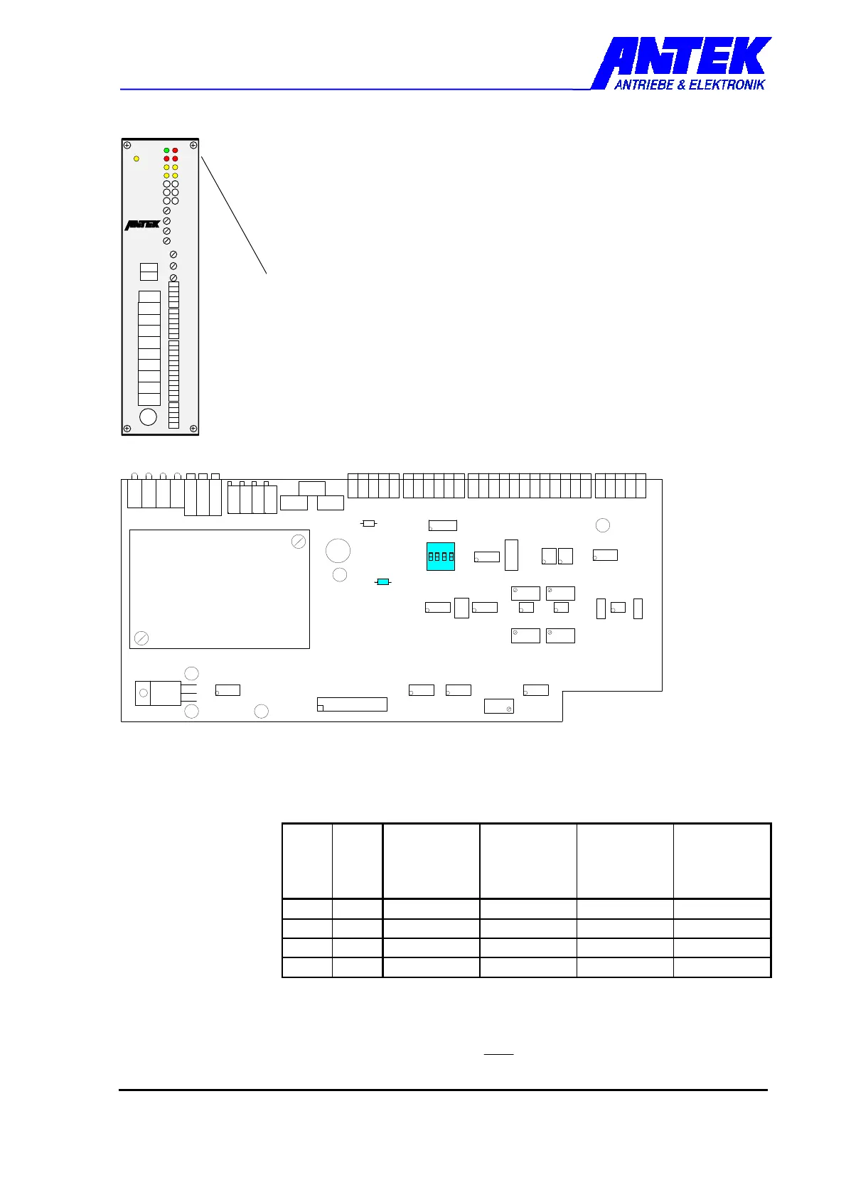
The drive control must be open for encoding. Disconnect drive control
from mains voltage for this purpose.
Loosen the 4 screws on the front panel corners and remove the front
panel together with control card.
Set the required encoding and re-assemble the drive control in
reverse order.
1
S1
2 3
4
C5
R97
A432-BS
Kommutierungsmodul
-off-
R161
S1-1, S1-2 Speed adjustment "n-max“ for
♦ permanently excited three-phase synchronous motors and
♦ permanently excited DC motors with EMF regulation
S1-1
S1-2
f-Out
[Hz]
ECE
4poleMotor
[min-1]
ECE
6poleMotor
[min-1]
DC
Motor-
voltage
[V]
ON ON 33 - 64 1000 - 1920
1280 - 1260
65 - 130
OFF ON 62 - 115 1860 - 3450
1240 - 2300
125 - 240
ON OFF
90 - 170 2700 - 5100
1800 - 3400
185 - 330
OFF OFF
135 - 250 4050 - 7500
2700 - 5000
250 - 450
The column for 6 pole motors applies to resolver feedback ECE10CM-02.
pn
Outf=frequencymotor
=−
n ... Speed in rpm
p ... Number of pole pairs
commutation module
 Loading...