Technical Documentation ECE10CM, DC10CM Page 19 of 39
4.4.5 Control Connections
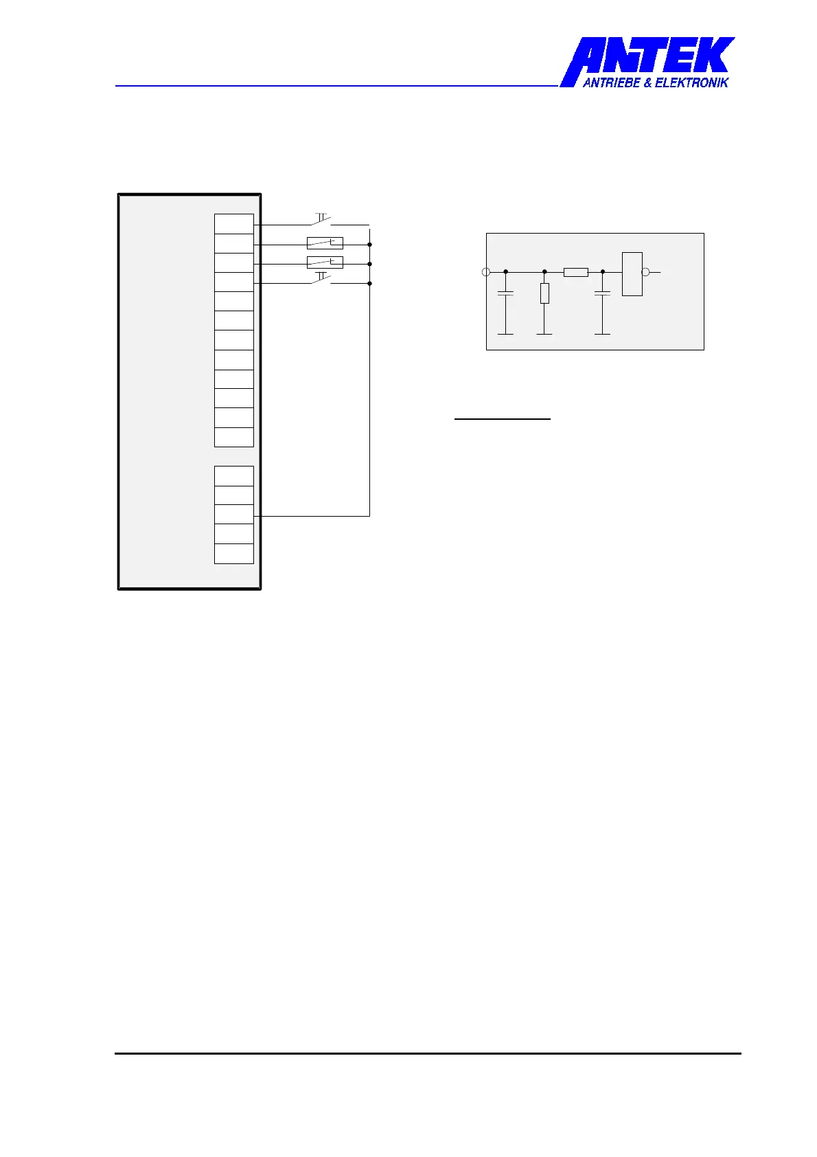
4.4.5.1 Digital Signal Connection
3
2
1
6
5
8
7
X
5
1
2
1
1
E
N
B
L
E
-
M
O
T
O
R
-
B
L
L
S
T
G
N
D
2
+
1
5
1
1
0
k
3
4
drive control
digital
input
internal circuit
Level Definition
HIGH = +12 ... + 35 VDC
LOW = 0 ... + 2VDC or open
reference potential: GND
input resistance: Ri = 10 kOhm
Ensure equal reference potential when
controlling via peripheral equipment!
ENABLE (X5-1) HIGH = control enabled, the direction of rotation is dependent on the
set point input X5-5/6
LOW = output stage disabled
ϑ
ϑϑ
ϑ-MOTOR (X5-2) Connection for motor protection contact (NC contact)
HIGH = motor temperature in working range
LOW = motor overheating, cut-out (output stage disabled) after
approx. 45 s time delay.
If no motor protection contact is used, terminal X5-2 must be
connected to HIGH potential e.g. +15 V X6-3.
ϑ
ϑϑ
ϑ-BALLAST (X5-3) Connection for thermal protection contact (NC contact)
HIGH = Ballast resistor in working range
LOW = Ballast resistor overheating, cut-out (output stage disabled)
occurs directly.
If no ballast resistor is used, terminal X5-3 must be connected to
HIGH potential e.g. +15 V X6-3.
RESET (X5-4) LOW-HIGH flank causes a resetting of the internal fault flip-flop (This
input can be switched in parallel to another control input in order to
minimise the wiring complexity)
A reset is carried out automatically with a time delay (approx. 1 s)
when applying the supply voltage to the control unit.
 Loading...