Technical Documentation ECE10CM, DC10CM Page 27 of 39
5.2 Measuring Points
n-SET Speed set point in accordance with set point integrator
Scaling:
100 %
GND Reference potential of all test jacks
I-max Maximum peak current I
max
Scaling: 1
A
V
I-SET Current set point (Speed regulator output)
Scaling: 1
A
V
I-ACT Current actual value (Phase current in Phase V)
Scaling: 2,5
A
V
n-ACT Speed actual value in accordance with internal f/U transformer
Scaling:
1500
p
1
min V
⋅
⋅
Speed actual value with variant DC10CM-01
(DC tachogenerator)
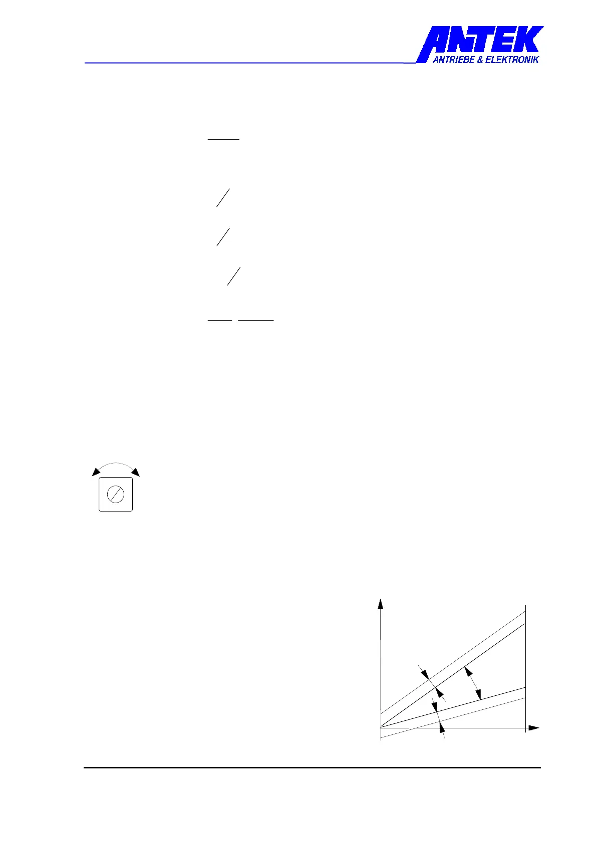
5.3 Trimmer
All of the trimmers required for the adjustment of the drive regulator to the respective
application are located on the unit boards. All of the trimmers are pre-set to the standard
parameters and/or the customer commissions so that the customer normally does not have
to re-adjust the trimmers.
Adjustment right = value increases
Adjustment left = value decreases
OFFSET Speed offset balancing
Put set point input to "0“.
Enable drive control,
i.e. set ENABLE to HIGH potential.
Set motor at standstill with "OFFSET“ trimmer.
p .. number of pole pairs
(ECE10CM-02: p=3)
-
n
-
m
a
x
1
0
V
 Loading...