F
F
r
r
o
o
n
n
t
t
P
P
a
a
n
n
e
e
l
l
C
C
o
o
n
n
n
n
e
e
c
c
t
t
o
o
r
r
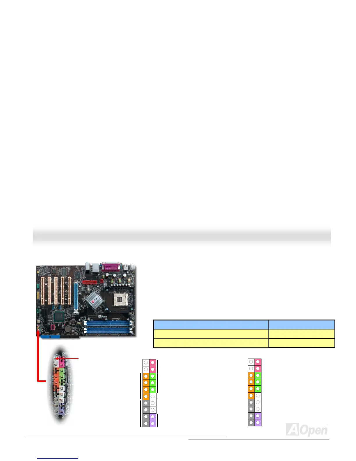
The pins of Front Panel Connector are painted in different colors with their respective
functions. Please attach the power LED, speaker, power and reset switch connectors
to the corresponding pins matched in same colors. If you enable “Suspend Mode” item
in BIOS Setup, the ACPI & Power LED will keep flashing or high light while the system
is in suspend mode.
Locate the power switch cable from your ATX housing. It is 2-pin female connector
from the housing front panel. Plug this connector to the soft-power switch connector
marked SPWR.
Suspend Type ACPI LED
Power on Suspend (S1) or Suspend to RAM (S3) Flashing for every second
Suspend to Disk (S4) The LED will be turned off
1
1
IDE LED
SPEAKER
Pin1
NC
NC
+5V
IDE LED
IDE LED
+5V
+5V
GND
NC
SPEAKER
SPWR
GND
ACPILED-
GND
ACPILED+
NC
NC
GND
RESET
GND
Power Switch
ACPI & Power LED
RESET