Rev. A2, 07/16 PG7
25
Automation Products Group, Inc.
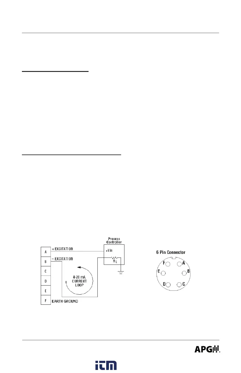
Wiring the PG7
4-20 mA Option (loop powered):
NOTE 1: The supply voltage must be sucient to maintain a minimum of 9
VDC after “dropping” voltage across the load resistance with the output at
20mA. Example: If RL = 250 ohm then the “drop” is 0.02 Amps X 250 ohm = 5
volts. Therefore power supply minimum is 5 V + 9 V = 14V.
NOTE 2: Completion of the earth ground (Pin F) is recommended for proper
circuit protection.
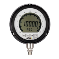
Battery Replacement:
Step 1: Press on the front bezel and turn counter-clockwise to release the
bezel from the gauge.
Step 2: Remove the front display to access the batteries.
Step 3: Replace the front display ensuring that the notch in the display
aligns with the tab on the gauge housing.
Step 4: Replace the bezel by lining up with the tabs on gauge while pressing
inward and twisting clockwise.
www. .com
information@itm.com1.800.561.8187