Rev. B2, 8/16 PG10
37
Automation Products Group, Inc.
Tel: 1/888/525-7300 • Fax: 1/435/753-7490 • www.apgsensors.com • sales@apgsensors.com
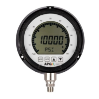
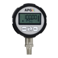
Wiring the PG10
Battery Replacement:
Step 1: Untwist the display locking ring (on the face of the gauge) counter-
clockwise until the ring releases the display from the gauge.
Step 2: Remove the front display to access the batteries.
Step 3: Replace the front display ensuring proper alignment and secure into
place using the locking ring.
5 3
6
8
2
4
1
7
8_Pin Connector Wiring:
L1
4-20 mA
8 Pin Connector
1 + Excitation
2 n/a
3
4 n/a
5 n/a
6
7
8
n/a
n/a indicates no pin connection
n/a
Case Gnd
- Excitation
L2
0-2 VDC
with Battery
Power Power
1 n/a
2
+ Output3
- Output
4 n/a
5 n/a
6
7
8
n/a
L3-C4
0-5 VDC
+ Excitation
-Exc/Out
+ Output
Relay 1 NC
Relay 1 NO
Relay 1/2 Com
L5
RS-485
+ Excitation
- Excitation
L3
0-5 VDC
+ Excitation
+ Output
- Excitation
n/a
Case Gnd
Relay 2 NC
Relay 2 NO
RS-485 A (+)
RS-485 B (-)
- Output
with External with 2 Tied
SPDT Relays
Power
with External
n/a
n/a
n/a
Case Gnd
n/a
n/a
n/a
Case Gnd
L1-C4
2 SPDT Relays
+ Excitation
- Excitation
Relay 1 Com
Relay 1 NC
Relay 1 NO
Relay 2 Com
Relay 2 NC
Relay 2 NO
with 4-20 mA
L4
External
Power
+ Excitation
- Excitation
n/a
n/a
n/a
n/a
Case Gnd
n/a
L4-C4
2 SPDT Relays
+ Excitation
- Excitation
Relay 1 Com
Relay 1 NC
Relay 1 NO
Relay 2 Com
Relay 2 NC
Relay 2 NO
with 4-20 mA
L5-C4
RS-485
+ Excitation
- Excitation
Relay 1 NO
Relay 1 Com
Relay 2 NO
Relay 2 Com
with 2 NO
Relays
RS-485 A (+)
RS-485 B (-)