API “The BOX” Operator’s Manual
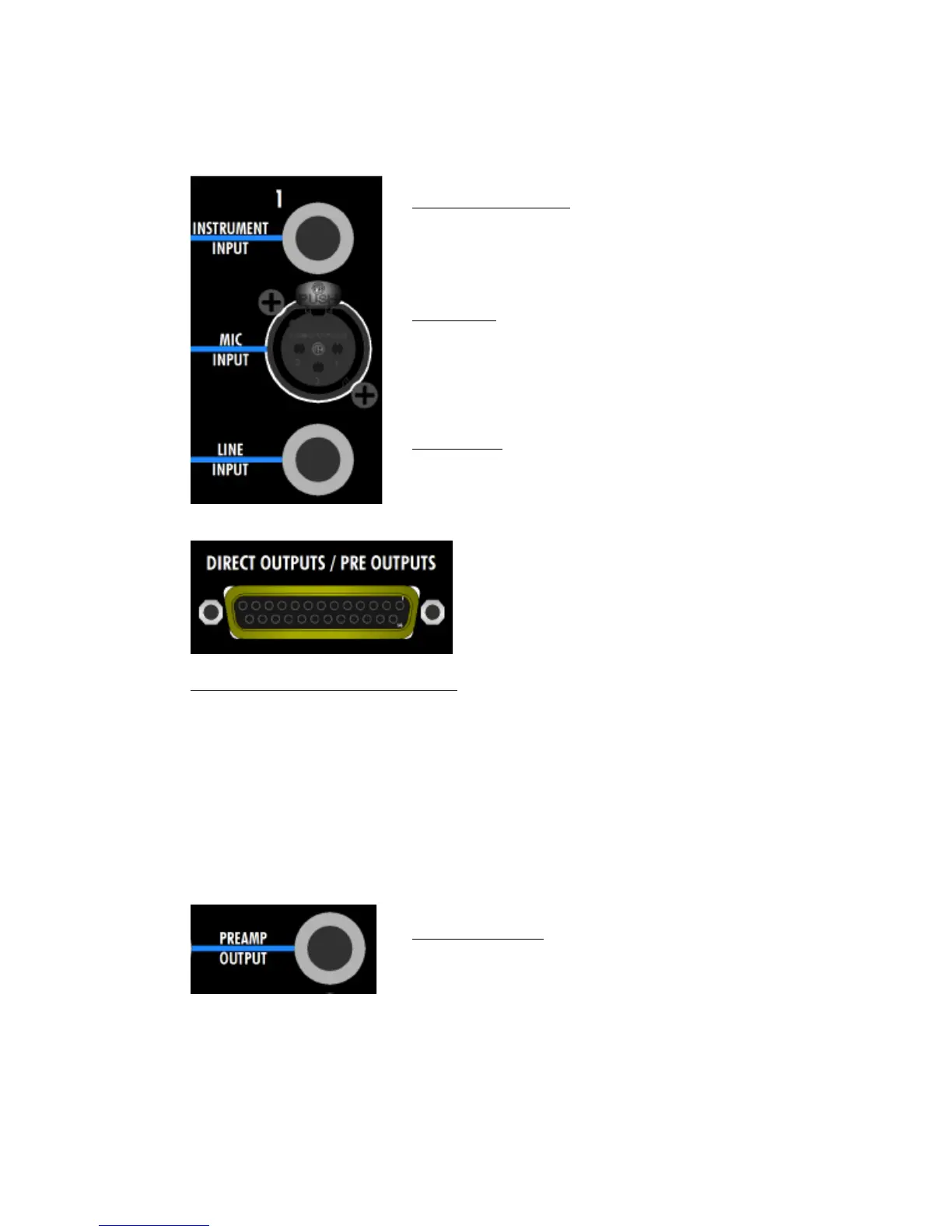
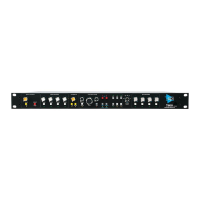
Rear Panel Preamp Connections
All four input channels have the same preamp input connections on the rear panel.
DIRECT OUTPUTS / PRE OUTPUTS: DB-25, balanced, low-impedance, line-level
• Outputs 1-4: Direct out (post-fader) or preamp output from input channels 1-4
o Fed post-fader/mute by default (direct output)
o Preamp output replaces post-fader output if DIR PRE is engaged
• Outputs 5 & 6: Insert send from input channels 1 & 2
• Outputs 7 & 8: Preamp outputs from input channels 3 & 4
• Standard pin-out: 1-4=direct or preamp outputs 1-4, 5-6=insert send 1-2, 7-8=preamp
outputs 3-4
In addition to the DB-25 connector, input channels 3 & 4 have a separate preamp
output that’s part of an extra set of connections that support the 500 slots.
INSTRUMENT INPUT: ¼” tip-sleeve, unbalanced, high-
impedance
• MIC must be engaged to use this input
• Replaces MIC signal as preamp input
MIC INPUT: 3-pin female XLR, balanced, low-impedance
• MIC must be engaged to use this input
• Provides phantom power when the 48v switch is
engaged
LINE INPUT: ¼” tip-ring-sleeve, balanced, low-impedance
• MIC must be disengaged to use this input
The DIRECT OUTPUTS / PRE OUTPUTS connector
carries direct or preamp outputs from input
channels 1-4, as well as the insert send from
input channels 1 & 2 and the preamp outputs
from input channels 3 & 4.
PREAMP OUTPUT: ¼” tip-ring-sleeve, balanced, low-
impedance, line-level
• Not available on input channels 1 & 2