Appendix Exi
5.4. Input inductance and capacity
a) Ci = 20nF, Li = 1,1mH
b) Ci=2,5nF, Li=18µH – for „Version SC”
5.6. Supply voltage min. 13,5VDC **
5.7. Load resistance:
from 28V linear supply
Ro max [] = for transmitter without display back lighting
from a source with “trapezial” or “rectangular” characteristic supply
Ro max [] =
*) barrier resistance
**) 16,5V for transmitter with display back lighting
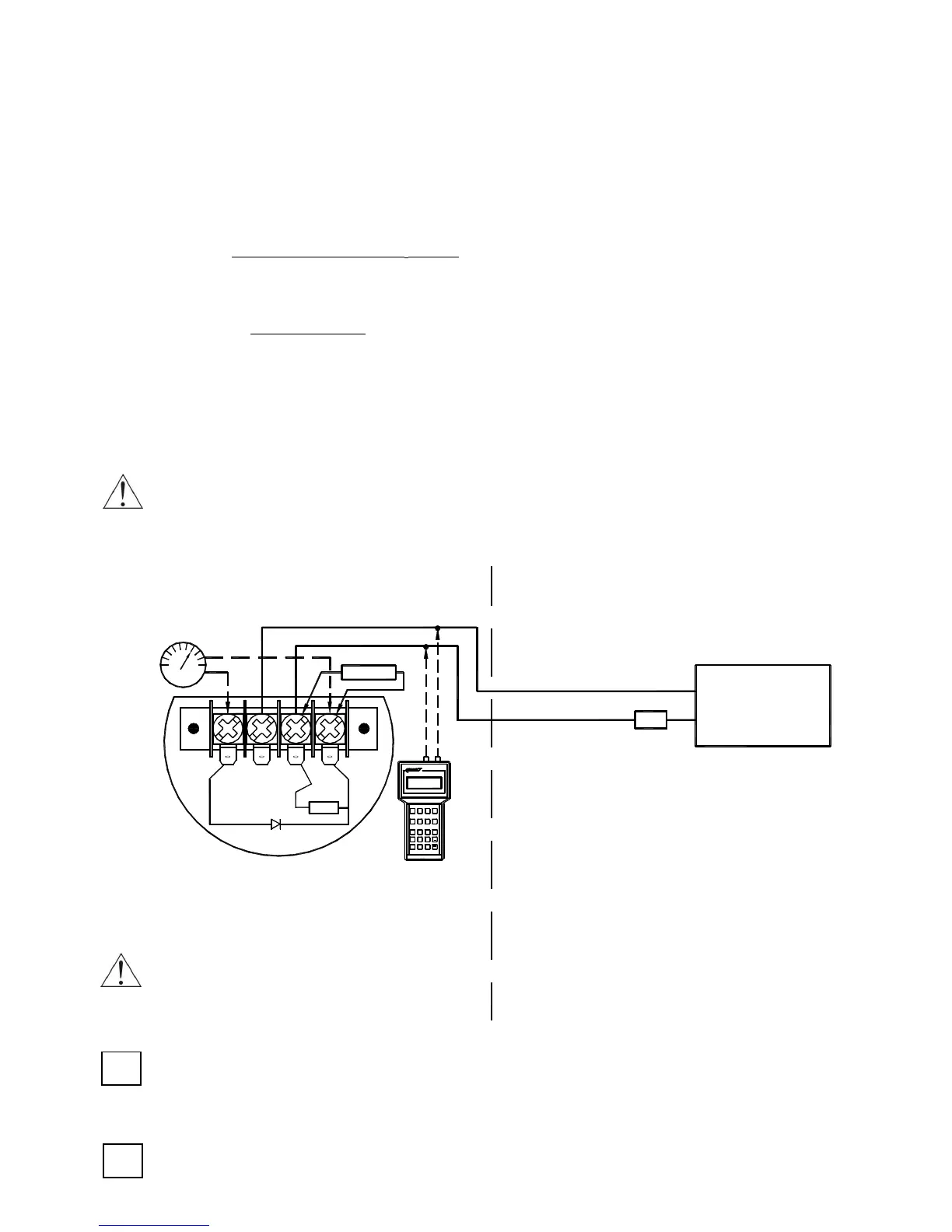
6. How to connect Ex transmitters APC…, APR… ?
The transmitter and other devices in the measuring loop should be connected in accordance
with the intrinsic-safety and explosion-safety regulations and the conditions for use in
dangerous areas.
Failure to observe the intrinsic-safety regulations can cause explosion and the resulting hazard
to people.
+
_
TEST
+
SIGNAL
Ex-Milliammeter
mA
_
Aplisens KAP-03Ex Communicator
RD
TEST
240 Ω
F1
PF
F4F3
F4PV
F2
RE
ABC
STU
7
JKL
4
1
@%&
08
GHI
9
+/
*
PQR
65
YZ#
DEF
MNO
VWX
2 3
.
Jumper
Ro
+
_
a Ex power supply
see p.5.
Safe area
≥ 250Ω
In hazardous areas, connections
to the control terminals must be
made using only instruments which
are permitted to be used in such areas.
Hazardous area
To measure the current in the transmitter without
disconnecting the signalling circuit, connect
a milliammeter to control sockets TEST+, TEST-.
The transmitter is equipped in additional communication resistor RD = 240
During normal operation terminals <Signal –> and <Test –> are shorted.
RD resistor is used when you wish to communicate with the transmitter locally (from its terminals)
and Ro < 250Ω. Terminals <Signal –> and <Test –> must be opened.
If the temperature of the medium exceeds Ta, then suitable separators such as membrane
separators or P-type siphon tubes must be used. Transmitter working temperature (Tp) must
conform to TpTa.
Usup. – 13.5V **
0,0225A
28V – 13.5V** – (300*
*
0,02A)
0,0225A
 Loading...