A1 28 DTR.APC.APR.ALW.03
(ENG)
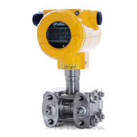
8.3.2. The APR-2000GALW transmitter can also be fitted with an adapter (Fig.17) creating a C-type connector,
designed for installation on a 3-valve or 5-valve manifold. Aplisens can also supply ready transmitters mounted
on valves.
8.4. APR-2000YALW. Installation and connections
The APRE-2000YALW level probes installed in places where liquid levels are measured in closed tanks, with
access to medium from top of tank as fig.15 and 10.2.6. Level probes should be installed in a vertical position.
8.5. APC-2000ALW/L…. Installation and connections
APC-2000ALW/L…. installed in places where liquid level is measurement: in wells, tanks, reservoirs, etc.
The transmitter sensor is immersed in measured medium. The sensor can be hung on the power cable by using
a APLISENS SG handle , but especially in the case of long cables, or if are opportunities of hooking protruding
elements when the cable is pulling up, it is recommended that the sensor suspended on a steel rope using the
sensor lug. If the sensor would be in the flow or turbulence of medium, should be assembled in the casing pipe
for example PVC made.
From sensor SG-25S remove the protective plate before its placing into medium.
During the installation the sensor should be protected from mechanical shocks
Sensor with cable with additional Teflon shield should be hung on a steel rope or on a cable (no fasten by
Teflon shield).
Pressure may be transmitted to the installed device only after checking that it has a measurement
range which properly corresponds to the value of the measured pressure, that gaskets have been
properly selected and fitted, and the connectors have been properly screwed tight.
Attempts to undo the screws or fixing connector pipes on a transmitter under pressure may
cause the medium to leak and create hazards for the personnel.
When disassembling the transmitter, it is necessary to disconnect it from the process pressure or
bring the pressure to atmospheric level, and to take particular care and precautions in case of
media which are highly reactive, caustic, explosive or otherwise hazardous to personnel.
If necessary, rinse out this part of the system.
Transmitters with flange diaphragm seals are to be installed on the corresponding counter flanges on the
facility.
It is recommended that the user matches the screw joints material to the pressure, temperature, flange
material and seal to ensure tightness of the flange joint in the expected operating conditions.
Screws complying with ISO 261 are to be used for flanges used in the APC..., APR... transmitters.
Additional data concerning the diaphragm seals are specified in the “DIAPHRAGM SEALS” catalogue cards.
9. ELECTRICAL CONNECTION
9.1. General recommendations
9.1.1. It is recommended that twisted pair cabling be used for the signal lines. If the transmitter and signal line
are subject to a large amount of electromagnetic interference, then shield pair cable should be used. The signal
wires should not run alongside network power supply cables or near to large electrically-powered devices.
The devices used together with the transmitters should be resistant to electromagnetic interference from the
transmission line in accordance with compatibility requirements. It is also beneficial to use anti-interference
filters on the primary side of the transformers, the power supplies used for the transmitters and apparatus used
in conjunction with them.
9.1.2. Wet or rising damp inside transmitter can cause its damage.
When the isolation of the wires in the cable gland is ineffective (for example, when single wires
are used) the opening of the gland should be carefully sealed with an elastic sealing compound
to obtain IP66 protection. It is useful to form the segment of the signal wire leading to the cable
gland into a protective loop to prevent condensation from running down in the direction of the
gland.
 Loading...