A1 45 DTR.APC.APR.ALW.03
(ENG)
15. FIGURES.
Input
circuitmodule
Sensing
1
+
_
system
Power supply/
measurement
min.250
Load resistance
Output
P
r
o
c
e
s
s
o
r
a/c
Converter
circuit
Modem
Communicator
filter
Noise
2
D
Ω
Memory
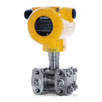
Fig. 1. APC...,APR... transmitters – block diagram.
Communicator or modem electrical connections to transmitter measuring lines.
For successful communication with transmitter the resistance in measuring loop, behind connected
device to communication, should be higher than 250. If necessary install the additional resistor in the
line. The communicator or modem connecting ways to the measuring loop are presented at diagrams.
During increasing of resistance in the measure loop at making the good transmission, is necessary to
make sure that the tension falls at sum resistances in the loop don't lower minimum tension at transmitter
terminals. (see p.5.1.1)
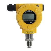
Fig.2. Electrical connections for APC...,APR... transmitters
BELL
202
RS 232
Communicator
Current loop
Switch box
JUMPER
supply
.
32
VWX
MNO
DEF
YZ#
5 6
PQR
*
+/
9
GHI
8 0
@%&
1
STU
4
JKL
ABC
7
RE PV F4PF
F2 F3 F4
RAPORT
+TEST
-TEST
-
+
SIGNAL
240
Ω
Power
Ro
mA
4÷20 mA
+
_
F1
Fig.2a. The link of transmitter and communicator or modem to current line by the switch box ( in case of the
resistance in current loop is higher than 250Ω).
 Loading...