A1 18 DTR.APC.APR.ALW.03
(ENG)
4. IDENTIFYING MARKS. ORDERING PROCEDURE
4.1. Every transmitter carries a rating plate containing at least the following information: CE mark, manufacturer
name, transmitter type, serial number, pressure range, static pressure limit, output signal, power supply voltage.
Version types and the method of specifying the desired product are described in the current “Information Cards”
and the Catalogue.
4.2. APC...APR...transmitters in Ex version or Exd version have additional markings as described in
DTR.APC.APR.ALW.03
(ENG)
Appendix Exi or Exd.
4.3. The rating plates of APC… , APR… transmitters in versions compliant with the PED pressure
directive contain the notified unit number 0062 next to the CE mark, as well as the designations
of certificates number:
CE-PED-H1D-APL 003-04-POL-rev… - for APC-2000ALW, module H1D + H1 (category IV)
CE-PED-H1D-APL 002-05-POL-rev… - for APR-2000ALW, module H1D + H1 (category IV)
CE-PED-H1-APL 001-11-POL
CE-PED-B-APL 001-09-POL,
CE-PED-D-APL 001-09-POL - for APC-2000ALW, APR-2000ALW, module B + D (category IV)
4.4. APC...APR... transmitters in realization for sea uses have additional information about signs
Location Classe and DNV Certificate No. A-11308.
4.5. The rating plates of APC-2000ALW transmitters in MID version contain MID Part Certificate
Number and information about realization according to EN 12405-1.
5. TECHNICAL DATA.
5.1. APC..., APR...- Common parameters
5.1.1. APC..., APR... Electrical parameters
Power supply voltages:
Standard versions 12 *) ÷ 55V DC,
Exi versions 13,5*) ÷ 28V DC see Appendix Exi
Exd versions 12 *) ÷ 45V DC see Appendix Exd
MID Exi versions 13,5*) ÷ 28V DC see Appendix MID, Exi
*
)
Backligth setting
of indicate increases the minimum supply voltage for all versions by 3V.
Output signal 4÷20mA + Hart rev.5.1
Communication with the transmitter to verify its configuration parameters is performed using a Hart signal. For
that, you can use the KAP-03 communicator for pressure transmitters or APLISENS modems: SH05 or Hart /
USB / Bluetooth, or another any Hart modem and your PC, and Report2 program
.
Resistance for communication (HART) min 240
Load resistance R
o
[
]
=
The maximum length of the connection cable 1500m
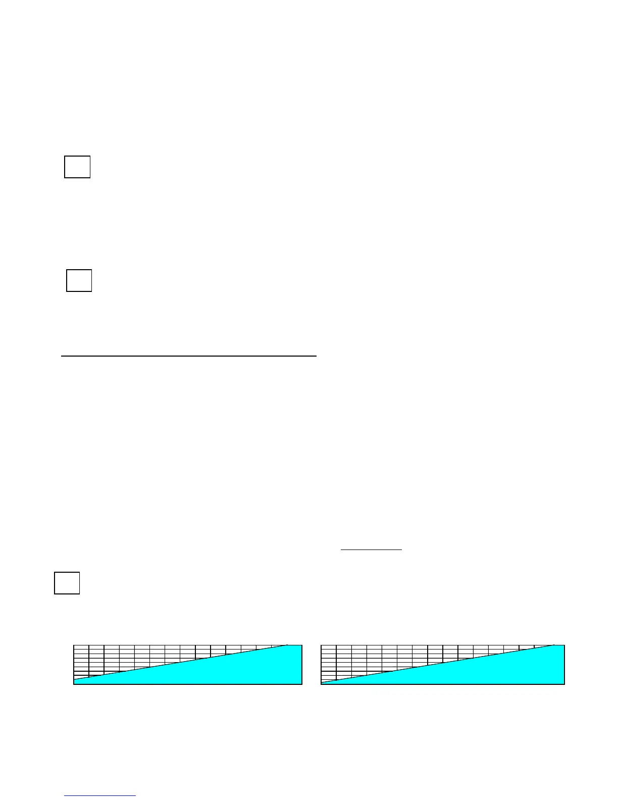
U
suply
min. = 12* + 0,0225xRo
[V]
for transmitters without backlighting (or read up from the chart below)
U
suply
min. = 15* + 0,0225xRo
[V]
for transmitters with backlighting (or read up from the chart below)
Ro [Ω] is a total resistance of the measuring line (current loop)
*)
to Exi option is necessary to insert to the formulas respectively: 13.5 and 16.5 V.
0 250 500 750 1000
10
15
20
25
30
35
40
45
Ro[ ]
Ω
Vmin [V]
Umin = f(Ro) z podwietleniem
0 250 500 750 1000
10
15
20
25
30
35
40
45
Ro[ ]
Ω
Vmin [V]
Umin = f(Ro) bez podwietlenia
50
55
50
55
1250
1500 1750
1250 1500 1750
Safe working area for normal transmitter (grid) upper colour area.
Output updating time 500ms
Additional electronic damping 0...30s
 Loading...