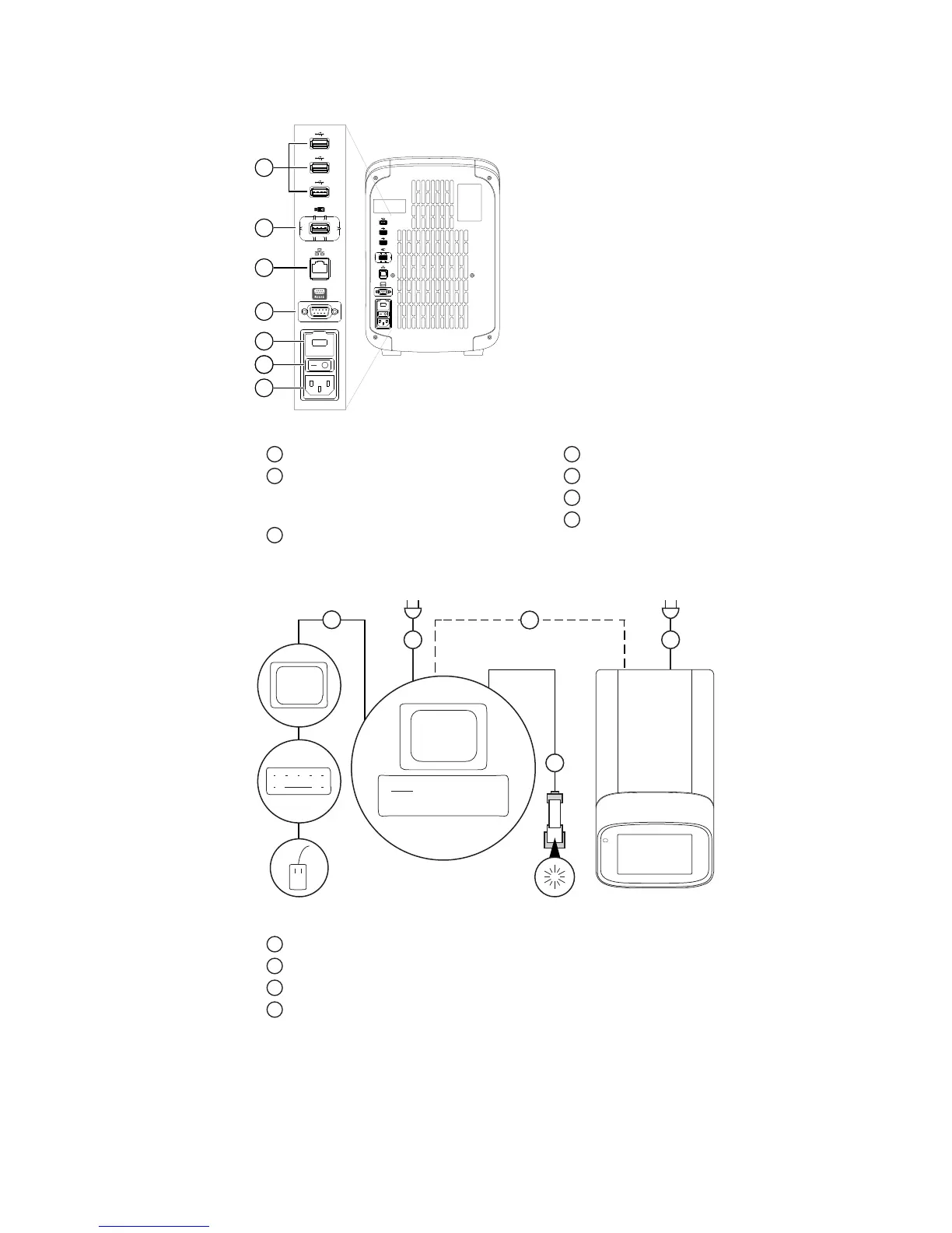
Figure 1 Ins
trument back panel
1
USB ports
2
WiFi USB port—Connect USB wireless
adapt
er for wireless network access
(ordered separately)
3
Ethernet Port—RJ45 port for
100/1,000 Mbps Ethernet c
ommunication
with the instrument
4
RS232 Port—For service use only
5
Fuse Cover
6
Power Switch
7
Power Port—100 to 240 VAC
Figure 2 Ins
trument‑to‑computer connections (minitower configuration)
1
Detachable power supply cord compatible with local power supply receptacle.
2
Connection between the computer and the instrument.
3
Connection between the computer and the monitor, keyboard, and mouse.
4
Connection between the computer and the
(optional)
handheld barcode scanner.
Instrument and
c
omputer
connections
Site requirements
6
QuantStudio
™
3 and 5 Real-Time PCR Systems Site Preparation Guide | MAN0010405 C.0