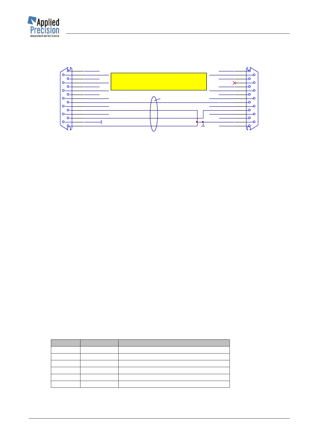
5.18.2 Dosage cable AP Reference Standard – AP Power Source
This dosage cable AP Reference Standard - AP Power Source is needed for dosing:
5.18.3 Preparation for dosage
• One of the 8 operating modes for active or reactive energy must be selected.
• Dosage energy or time must be defined.
• During a dosage function is recommended to not use auto range system.
• The load values for the test: current, voltage and phase angle must be defined and switched
on at the source.
• Definition of initial and end status of relay contacts SU / SI must be defined.
• The status before start, after start and after stop of dosage of the contacts as well as switching
delay times for each contact can be defined. It can be defined that only current is switched off
and on or that both voltage and current are switched off.
5.18.4 Running of dosage
After initiating dosage (with menu item or command “Start” or “Init”) the relay contact disconnect the
load regarding the definition made to allow writing down the initial reading of the energy registers. After
starting dosage (with menu item or command “Start”) the dosage is immediately started and the relay
contacts are closed regarding the definition. The Device now counts the predefined amount of energy
or time.
If the amount of energy or time is reached or if the dosage is stopped earlier (with menu item or
command “Stop”) the contacts are opened again to switch off the power source regarding the definition.
Now the final reading of the energy registers can be read and the error can be calculated. Dosage
function is ended by menu item or command “Stop” or “Cancel”.
5.18.5 Dosage Modes
There are 6 Dosage Modes: