EasyManuals Logo

Applied Precision RS 2130 User Manual

Default Icon
59 pages
To Next Page IconTo Next Page
To Previous Page IconTo Previous Page
Page #5 background imageLoading...
Page #5 background image
Reference Standard RS 2x30, RS 1x30
User’s Guide
www.appliedp.com RS-UG91-EN
5
2. Device Description
2.1 Introduction
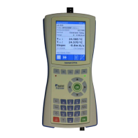
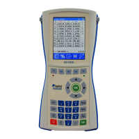
The Reference Standard is the single-phase (RS 2110) and three-phase (RS 2310) version of
precision meter for electrical power and energy measurement.
The Reference Standard is designed to meet all requirements put on a reference standard in a
single- and three-phase electricity meter testing and calibration systems. The Reference Standard can
be set to any real or artificial mode of operation in three phase system and is capable to evaluate the
individual quantities per phase and the three-phase cumulative quantities as well.
The Reference Standard is based on precision 24-bit A/D conversion and digital signal processing
technology enabling accurate evaluation of all main and informative quantities. Beyond measurement
of all kinds of power, voltage, current and phase, the meter measures the harmonic content and
distortion of the input signals.
The Reference Standard has independent input circuits for the individual phases. This feature in
combination with the possibility to assign the impulse output to any combination of the input channels
(phases) enables for example to use the device in one phase system while the free channels can gather
additional information like power consumption of the current and voltage circuits for contact error
monitoring.
The Reference Standard makes harmonic analyze of the voltage and current spectrum and
measures and computes these quantities shown in display of the device:
Quantity
Description
Code
Unit
Voltage
Effective value of the alternating voltage
U
V
Current
Effective value of the alternating current
I
A
Phase U
Phase offset between U
x
and U
1
φ
U
°
Phase I
Phase offset between U and I
φ
I
°
Frequency
Frequency
f
Hz
Power Factor
Power factor
Λ
-
Distortion of Voltage
Distortion of voltage
DF
U
%
Distortion of Current
Distortion of current
DF
I
%
Active Power
Active power
P
W
Reactive Power
Reactive power
Q
VAr
Apparent Power
Apparent power
S
VA
Phase-to-phase Voltage
Phase-to-phase voltage
U
pp
V
Sum of Active Power
Sum of active powers in all channels
ΣP
W
Sum of Reactive Power
Sum of reactive powers in all channels
ΣQ
VAr
Sum of Apparent Power
Sum of apparent powers in all channels
ΣS
VA
Sum of square Voltage / 1
Sum of square voltage / 1
ΣsqrU/1Ω
W
Sum of square Current / 1
Sum of square current / 1
ΣsqrI/1Ω
W
Active Energy
Active Energy
E
p
kWh
Reactive Energy
Reactive Energy
E
q
kVArh
Apparent Energy
Apparent Energy
E
s
kVAh
Impedance Module
Module of impedance
Z
Impedance Phase
Phase of impedance
φ
°
Impedance Real Part
Real part of impedance
R
Impedance Imaginar Part
Imaginar part of impedance
X
Net Factor
Net power factor
-
Default configuration shows in main screen these quantities: P,U,I,f,φ,DF
U
,DF
I

Table of Contents

Questions and Answers:

Question and Answer IconNeed help?

Do you have a question about the Applied Precision RS 2130 and is the answer not in the manual?

Applied Precision RS 2130 Specifications

General IconGeneral
BrandApplied Precision
ModelRS 2130
CategoryMeasuring Instruments
LanguageEnglish

Related product manuals