APsystems YC500-A Installation/User Manual 8
YC500 number per branch
2 3 4 5 6 7* 8 9
EXTERNAL WIRE
SIZE (AWG) MAXIMUM EXTERNAL CABLE LENGTH (ft)
12 370.7 237.1 167.9 124.3 93.6 70.2 51.4 35.7
10 593.1 379.4 268.6 198.9 149.7 112.3 82.3 57.1
8 926.8 592.9 419.6 310.7 233.9 175.5 128.6 89.3
6 1482.8 948.6 671.4 497.1 374.3 280.8 205.7 142.9
*7 is the maximum number/branch with a 20 amp breaker
Step 2 – Attaching the APsystems microinverters to the
racking or the PV module frame
A. Mark the location of the microinverter on the rack, keeping in
mind the PV module junction box or any other obstructions.
B. Mount one microinverter at each of these locations using
hardware recommended by your module racking vendor.
C. GROUNDING WASHER: If using the appropriate grounding
washer (check with a licensed electrician), attach the grounding
washer between the PV racking frame and the microinverter.
WARNING: Prior to installing any of the microinverters, verify that
the utility voltage at the point of common connection matches the
voltage rating on the microinverter label.
Figure 5
APsystems YC500A/I Installation/User Manual
Installation Procedures
Step 2 - Attaching the APsystems Microinverters to the
Racking or the PV Module Frame
a. Mark the location of the Microinverter on the rack, with respect to
the PV module junction box or any other obstructions.
b. Mount one Microinverter at each of these locations using hardware
recommended by your module racking vendor.
c. GROUNDING WASHER: If using the appropriate grounding washer
(check with a licensed electrician), attach the grounding washer between
the frame and the Microinverter.
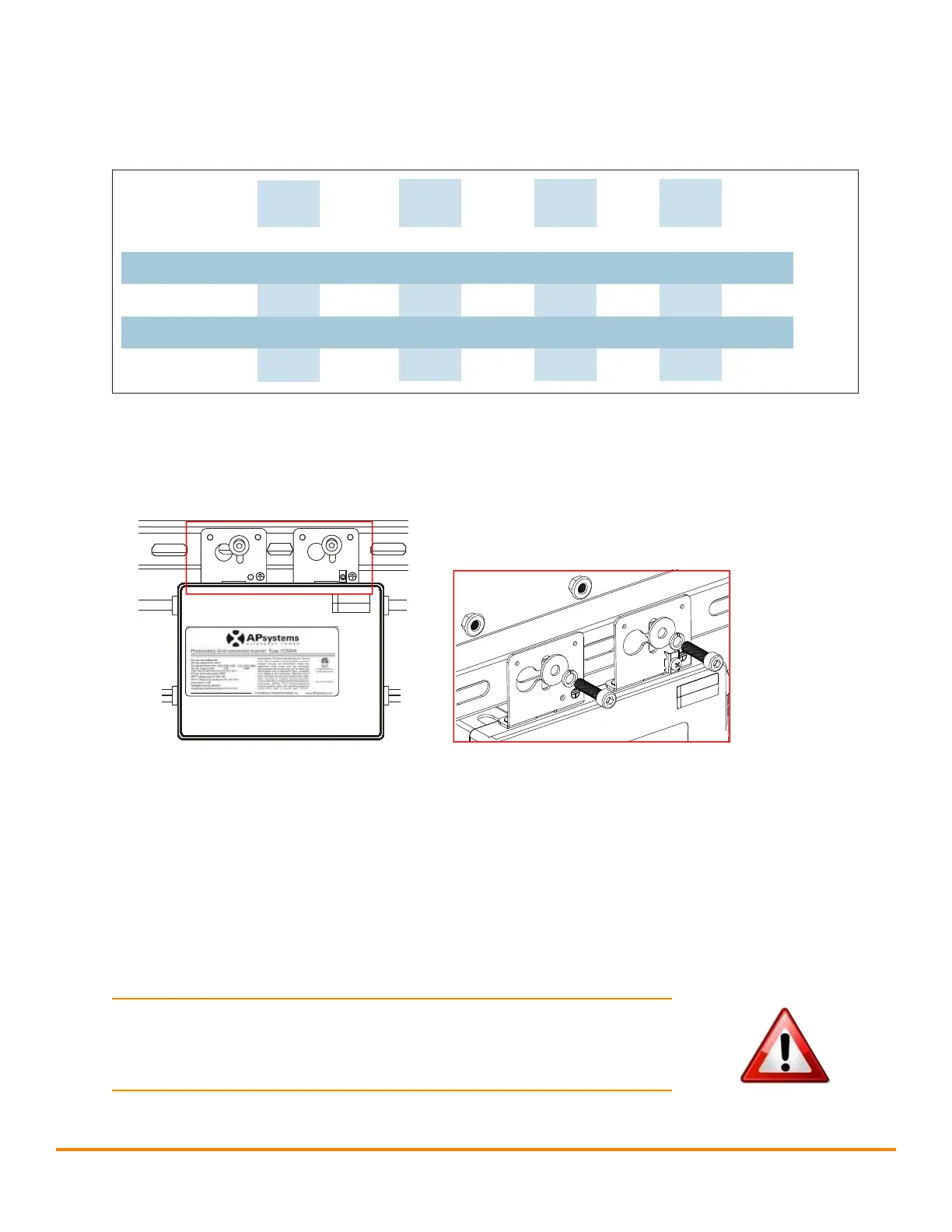
Option 1:
A
B
Figure 4
Option:2
Figure 5
WARNING: Prior to installing any of the microinverters, verify
that the utility voltage at the point of common connection matches
the voltage rating on microinverter label.
WARNING:
Do not mount the Microinverter in a location that
allows exposure to direct sunlight. Allow a minimum of 3/ 4’’(1.5cm.)
between the roof and the bottom of the Microinverter to allow
proper air flow.