APsystems YC500-A Installation/User Manual 10
WARNING: Ensure that all AC and DC wiring is correct. Check that
none of the AC and DC wires are pinched or damaged. Be sure that
all junction boxes are properly closed.
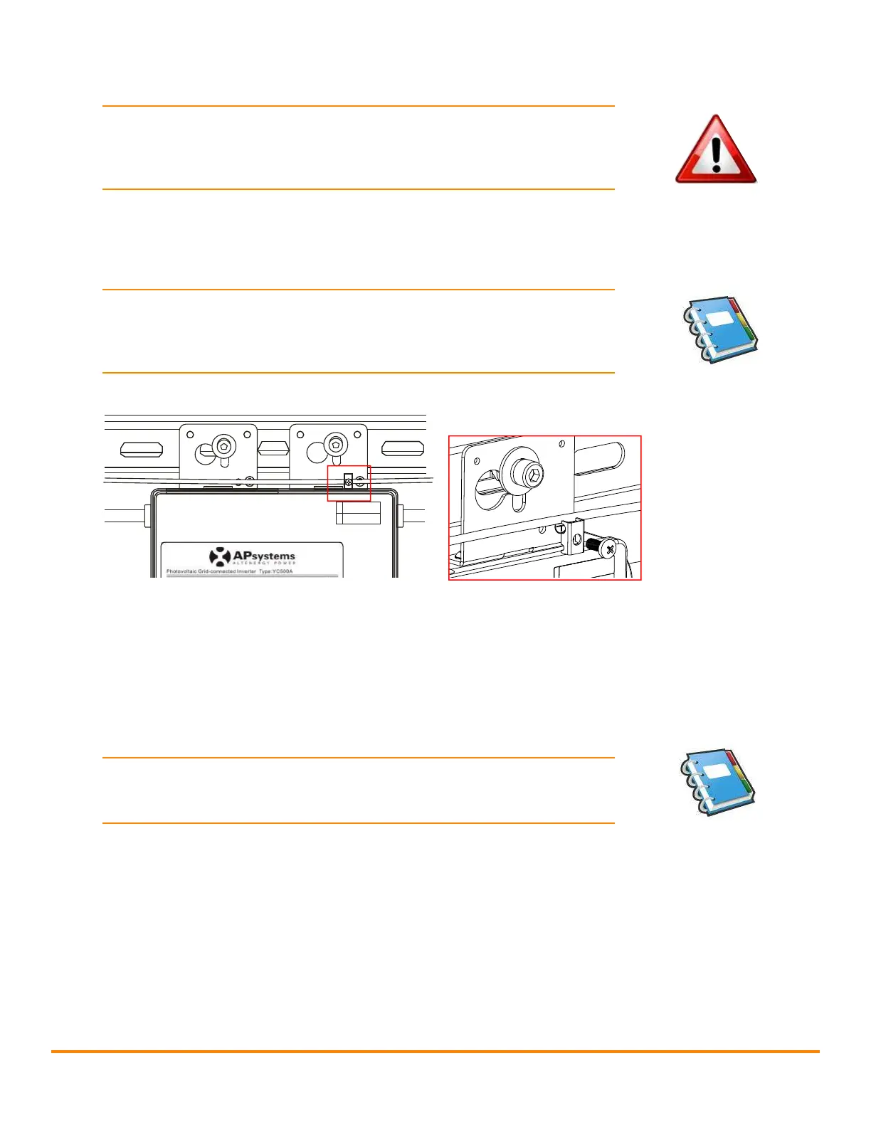
Step 4 - Ground the system
NOTE: If you already used grounding washers (WEEB) to ground the
microinverter chassis to the PV module racking as described in Step
2C, skip this step.
Each APsystems microinverter comes with a ground clamp that can
accommodate a single #6 awg strand and #4 awg solid conductor.
Check your local electrical code for grounding conductor sizing
requirements. Connect the grounding electrode conductor to the
microinverter ground clamp.
NOTE: The AC output neutral is not bonded to ground inside the
microinverter.
APsystems YC500A/I Installation/User Manual
Installation Procedures
Step 4 - Ground the System
If you already use grounding washers (WEEB) to ground the Microinverter
chassis to the PV module racking as described in Step 2, skip this step.
Figure 9
Each APsystems Microinverter comes with a ground clamp that can
accommodate a single #6 awg strand and #4 awg solid conductor. Check
your local electrical code for grounding conductor sizing requirements.
Connect the grounding electrode conductor to the microinverter ground
clamp.
NOTE: The AC output neutral is not bonded to ground inside the
microinverter.
Step 5 - Connecting APsystems Microinverters to the PV
Modul e
Connect the DC cables from the PV Modules to the Microinverter per the
diagram below:
NOTE:
When plugging in the DC cables, the Microinverter should
immediately blink green three times. This will happen as soon as
the cables are plugged in and will show that the Microinverter is
functioning correctly. This entire check function will start and end
within 5 seconds of plugging in the unit, so pay careful attention to
these lights when connecting the DC cables.
Figure 7