APsystems YC500-A Installation/User Manual 9
WARNING: Do not mount the microinverter in a location that allows
exposure to direct sunlight. Allow a minimum of 3/4” (1.5 cm.) between
the roof and the bottom of the microinverter to allow proper air ow.
NOTE: Connecting cables (steps 3-5) can be done in any order but DO
NOT energize the utility power grid until all the steps are completed.
Step 3 – Connecting APsystems microinverters to
the PV module
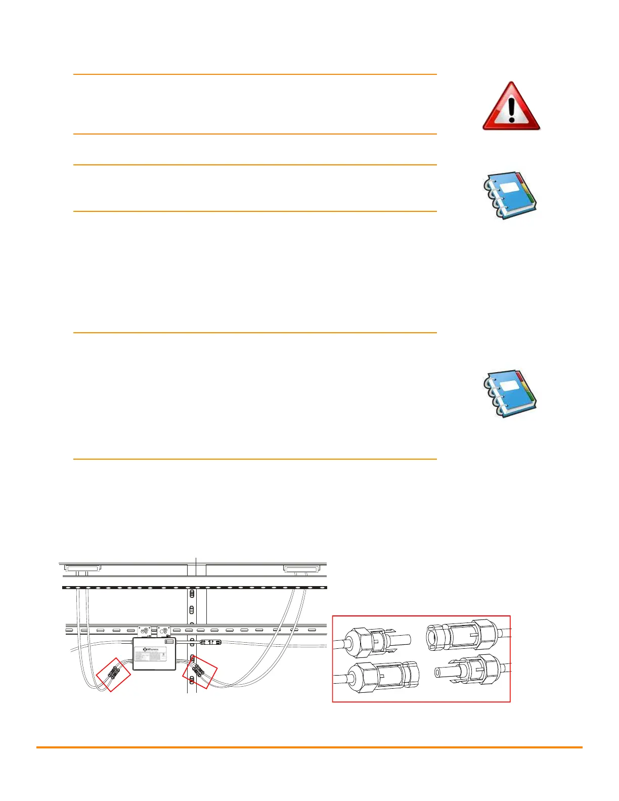
Connect the DC cables from the PV modules to the microinverter per the
diagram below:
Note: When plugging in the DC cables, the microinverter should
immediately blink red then green three times. This will happen as
soon as the cables are plugged in and will show that the microinverter
is functioning correctly. This entire check function will start and end
within 5 seconds of plugging in the unit, so pay careful attention to
these lights when connecting the DC cables. This only occurs when DC
voltage is rst applied. The LED will not ash when the second panel
is connected.
9
Figure 6
Photovoltaic panels
and microinverter DC
input cable connection
MC4 Connectors
APsystems YC500A/I Installation/User Manual
Installation Procedures
Step 4 - Ground the System
If you already use grounding washers (WEEB) to ground the Microinverter
chassis to the PV module racking as described in Step 2, skip this step.
Figure 9
Each APsystems Microinverter comes with a ground clamp that can
accommodate a single #6 awg strand and #4 awg solid conductor. Check
your local electrical code for grounding conductor sizing requirements.
Connect the grounding electrode conductor to the microinverter ground
clamp.
NOTE: The AC output neutral is not bonded to ground inside the
microinverter.
Step 5 - Connect ing APsystems Microinverters to the PV
Module
Connect the DC cables from the PV Modules to the Microinverter per the
diagram below:
NOTE:
When plugging in the DC cables, the Microinverter should
immediately blink green three times. This will happen as soon as
the cables are plugged in and will show that the Microinverter is
functioning correctly. This entire check function will start and end
within 5 seconds of plugging in the unit, so pay careful attention to
these lights when connecting the DC cables.
AB