APsystems YC500-A Installation/User Manual 11
Step 5 - Connecting the APsystems microinverter to the
PV module
A. Check the microinverter datasheet for the maximum allowable
number of microinverters on one AC branch circuit.
B. Plug the AC female connector of the rst microinverter into the
male connector of the next microinverter, and so on, to form a
continuous AC branch circuit.
C. Install a protective end cap on the open AC connector of the last
microinverter in the AC branch circuit.
WARNING: Do NOT exceed the maximum number of microinverters
in an AC branch circuit, as displayed on the unit label.
Figure 9
APsystems YC500A/I Installation/User Manual
Installation Procedures
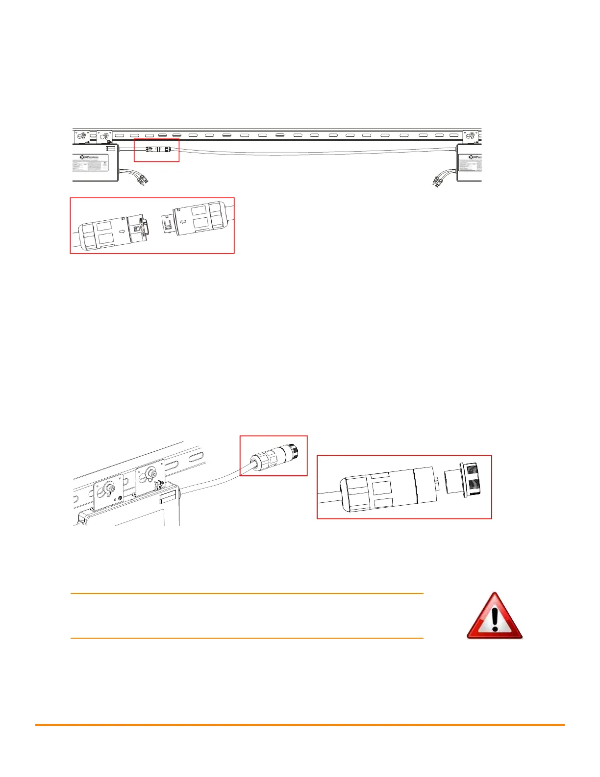
Step 3 - Connecti ng the APsystems Microinverter AC Cables
A
B
Figure 6
Best Practice: Use screwdriver to split the Main connectors.
Figure 7
a. Check the Microinverter technical data for the maximum
allowable number of Microinverters on each AC branch circuit.
b. Plug the AC female connector of the first Microinverter into the male
connector of the next Microinverter, and so on, to form a continuous
AC branch circuit.
c. Install a protective end cap on the open AC connector of the last
Microinverter in the AC branch circuit.
Figure 8
WARNING: Do NOT exceed maximum number of Microinverters
in an AC branch circuit, as displayed on the Technical Data page
(p.18) of this manual.
NOTE:
Please contact with ALTENERGY POWER SYSTEM Inc for
the purchase of AC extended cables when microinverters which are
installed space far and AC cable is not long enough.
APsystems YC500A/I In stallation/User Manual
Installation Procedures
Step 3 - Connecting the APsystems Microinverter AC Cables
Figu re 6
Best Practice: Use screwdriver to split the Main connectors.
Figure 7
a. Check the Microinverter technical data for the maximum
allowable number of Microinverters on each AC branch circuit.
b. Plug the AC female connector of the first Microinverter into the male
connector of the next Microinverter, and so on, to form a continuous
AC branch circuit.
c. Install a protective end cap on the open AC connector of the last
Microinverter in the AC branch circuit.
Figure 8
WAR NING: Do NOT exceed maximum number of Microinverters
in an AC branch circuit, as displayed on the Technical Data page
(p.18) of this manual.
NOTE:
Please contact with ALTENERGY POWER SYSTEM Inc for
the purchase of AC extended cables when microinverters which are
installed space far and AC cable is not long enough.
Figure 8