8
6
Fit the elbows to the valve body hand tight, ensuring that the rubber washers are correctly engaged (these are supplied in
the screw pack).
7
If the removal and replacement of the factory fitted regulator is necessary, undo the four screws securing the cartridge
assembly to the valve body and remove the cartridge, noting the gasket orientation.
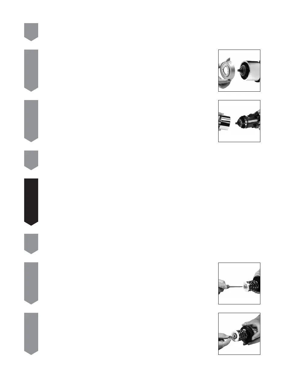
8
Remove the flow regulator assembly from inside of the filter in the rear of the cartridge T tube,
using a small flat bladed screwdriver if necessary.
9
Remove the relevant replacement regulator assembly from the packaging and position in the hot
inlet filter in the rear of the T tube, ensuring the O ring faces the incoming flow of water.
5
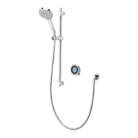
Carefully remove the shroud from the valve assembly.
3
Carefully remove the valve from its packaging and retain the mortar guard for later use.
4
Set the temperature lever to the mid-blend (12 o’clock) position as a point of reference. Undo the
four temperature screws securing the temperature lever to the valve and remove the temperature
lever.
!
IF FITTING AN OPG3111, GRAVITY OPTO OR AN OPH3111 HIGH PRESSURE OPTO, PLEASE PROCEED TO STEP 13.
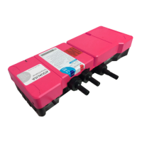
If the valve is being installed for use with a gas fired instantaneous (multipoint) water heater or a combination boiler, an
OPC3100 system should be fitted. The PINK cartridge is factory fitted with a YELLOW flow regulator in the hot inlet port,
suitable for use with an 80,000 Btu rated combi boiler. If fitting to a system supplied by a 100,000 Btu combi boiler, the
regulator should be replaced by a OLIVE regulator. If fitting to a system supplied by a 120,000 Btu combi boiler, the
regulator should be replaced by a BLUE regulator. The replacement regulators are supplied as part of the system
components.