EasyManuals Logo

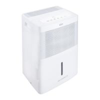
Argo ALICE 13 User Manual

Argo ALICE 13
60 pages
To Next Page IconTo Next Page
To Previous Page IconTo Previous Page
Page #18 background imageLoading...
Page #18 background image
Service Manual
Technical Information
16
5.
Electrical Part
5.1 Wiring Diagram
Instruction
Symbol
Symbol Color
Symbol
Symbol Color
Symbol
Name
WH
White
GN
Green
CAP
Jumper cap
YE
Yellow
BN
Brown
COMP
Compressor
RD
Red
BU
Blue
Grounding wire
YEGN
Yellow/Green
BK
Black
/
/
VT
Violet
OG
Orange
/
/
These wiring diagrams are subject to change without notice; please refer to the one supplied with the unit.
78%(
7(03 6(1625
/,48,'
/(9(/ 6:,7&+
57
)$1
02725
0
$3
78%(
&1
$3 0$,1
&1
<(*1
%2$5'
',63/$<
%2$5'
3(
&1
&1
.
&
&1
$& /
&203
1
1
%1 %.
/
%8 :+
<(*1 *1
67
+80,',7< 6(1625
5'
<(
%8
1
32:(5
3(
&
&
6
&203
%8
5
600007061656
<(*1
3(
&203

Questions and Answers:

Question and Answer IconNeed help?

Do you have a question about the Argo ALICE 13 and is the answer not in the manual?

Argo ALICE 13 Specifications

General IconGeneral
Airflow115 m³/h
DisplayLED
Noise level43 dB
Product colorWhite
Built-in displayYes
Water tank capacity3 L
Suitable for room area up to15 m²
Suitable for room volume up to- m³
AC input voltage220 - 240 V
AC input frequency50 Hz
Power consumption (typical)220 W
Operating temperature (T-T)5 - 32 °C
Operating relative humidity (H-H)35 - 80 %
Weight and Dimensions IconWeight and Dimensions
Depth225 mm
Width353 mm
Height496 mm
Weight11500 g

Related product manuals