EasyManua.ls Logo

Argo ALICE 13 User Manual

Argo ALICE 13
60 pages
To Next Page IconTo Next Page
Page #1 background imageLoading...
Page #1 background image
ALICE 13
ALICE 17
V 10/19
SERVICE MANUAL
DEHUMIDIFIER
EN
Question and Answer IconNeed help?

Do you have a question about the Argo ALICE 13 and is the answer not in the manual?

Argo ALICE 13 Specifications

General IconGeneral
Airflow115 m³/h
DisplayLED
Noise level43 dB
Product colorWhite
Built-in displayYes
Water tank capacity3 L
Suitable for room area up to15 m²
Suitable for room volume up to- m³
AC input voltage220 - 240 V
AC input frequency50 Hz
Power consumption (typical)220 W
Operating temperature (T-T)5 - 32 °C
Operating relative humidity (H-H)35 - 80 %
Weight and Dimensions IconWeight and Dimensions
Depth225 mm
Width353 mm
Height496 mm
Weight11500 g

Summary

INTRODUCTION

Notices

General Safety Instructions

General safety instructions to avoid risks to people and property.

Manual Symbols Guide

Explanation of symbols used throughout the manual for clarity and safety.

Minimum Room Size

Basics in RAC

Checks for Leakage

Direct Leak Detection Methods

Various direct methods to detect refrigerant leaks.

Indirect Refrigerant Detection Methods

Methods for detecting refrigerant leaks indirectly.

HC R290 Refrigerant Issues

HC R290 Refrigerant Basics

Fundamental properties and characteristics of HC R290.

HC R290 Properties and Parameters

Key physical and chemical properties of HC R290 refrigerant.

Flammability

Safety Data

R290 Hazard Identification

Identification of hazards associated with R290 refrigerant.

First Aid Measures

Fire Fighting Measures

Accidental Release Procedures

Emergency Actions for Release

Immediate steps for safety during an accidental release.

Post-Release Actions

Subsequent actions after immediate safety measures are taken.

Gas Leak Detection Procedures

Part I: Technical Information

1. Summary

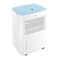
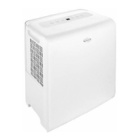
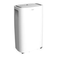
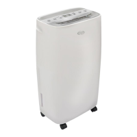
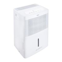
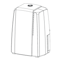
Overview of the dehumidifier unit and its models.

2. Specifications

Outline and Dimension Diagram

4. Refrigerant System Diagram

Dehumidifier Operation Principle

Explanation of how the dehumidifier removes moisture from the air.

5. Electrical System Information

Wiring Diagram

Schematic showing the electrical connections of the unit.

5.2 PCB Printed Diagram

PCB Main Board Views

Top and bottom views of the main PCB with component labels.

Display Board Layout

Display Board Views

Top and bottom views of the display board with component labels.

6. Functions and Controls

6.1 Control Panel Operation

Detailed instructions for operating the control panel.

Other Operational Notes

6.2 Basic Mode Functionality

System Functions and Safety Features

Covers drying mode, humidity range, and unit protection features.

Control Features and Indicators

Part II: Maintenance

7. Maintenance Notes and Precautions

Important notes and safety precautions before performing maintenance.

Electrical and Refrigerant Safety

Covers electrical and refrigerant safety during maintenance.

R290 Refrigerant Information

Maintenance Tools Overview

8. Operation and Maintenance

8.1 Water Drainage Options

Methods for draining collected water from the unit.

8.2 Cleaning and General Maintenance

Cleaning Instructions

Includes grille, case, and air filter cleaning instructions.

Pre-Season Checks and Storage

9. Maintenance Procedures

9.1 Maintenance Safety Principles

Fundamental safety rules for performing maintenance.

9.2 Maintenance Preparation

Steps to prepare the environment and unit before maintenance.

9.3 Maintenance Cautions

Electrical and Refrigerant Cautions

Cautions for electrical parts and refrigeration system maintenance.

9.4 Error Codes and Causes

9.5 Malfunction Detection Flowcharts

Temperature Sensor Malfunction Diagnosis

Troubleshooting flowchart for temperature sensor errors.

Humidity Sensor Malfunction Diagnosis

Insufficient Refrigerant Diagnosis

High-Temperature Overload Diagnosis

9.6 Common Malfunction Troubleshooting

Troubleshooting: Unit Won't Start

Troubleshooting steps when the unit fails to start.

Troubleshooting: Poor Dehumidification & Fan

Troubleshooting: Compressor, Leakage, & Sound

10. Exploded View and Parts List

11. Disassembly and Component Removal

Initial Disassembly Steps

Steps from before disassembly to removing the front panel.

Component Removal Steps

Steps for removing rear case, top cover, air duct, and electric box.

Appendices

Temperature Conversion Chart

Conversion chart for Celsius and Fahrenheit temperatures.

Temperature Sensor Resistance Data

Related product manuals