EN – 12
ATTACHMENT DRIVE BELT
REPLACEMENT
Remove Attachment Drive Belt
NOTICE: Save all hardware for reinstallation.
1. Stop engine, remove key and wait for all moving parts
to stop and for hot parts to cool.
2. Disconnect spark plug wire from engine.
3. Separate auger housing from frame. See Separate
Auger Housing from Frame on page 10.
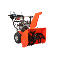
See Figure 12.
4. Remove attachment drive belt from attachment drive
pulley.
Install Attachment Drive Belt
1. Install belt onto attachment drive pulley.
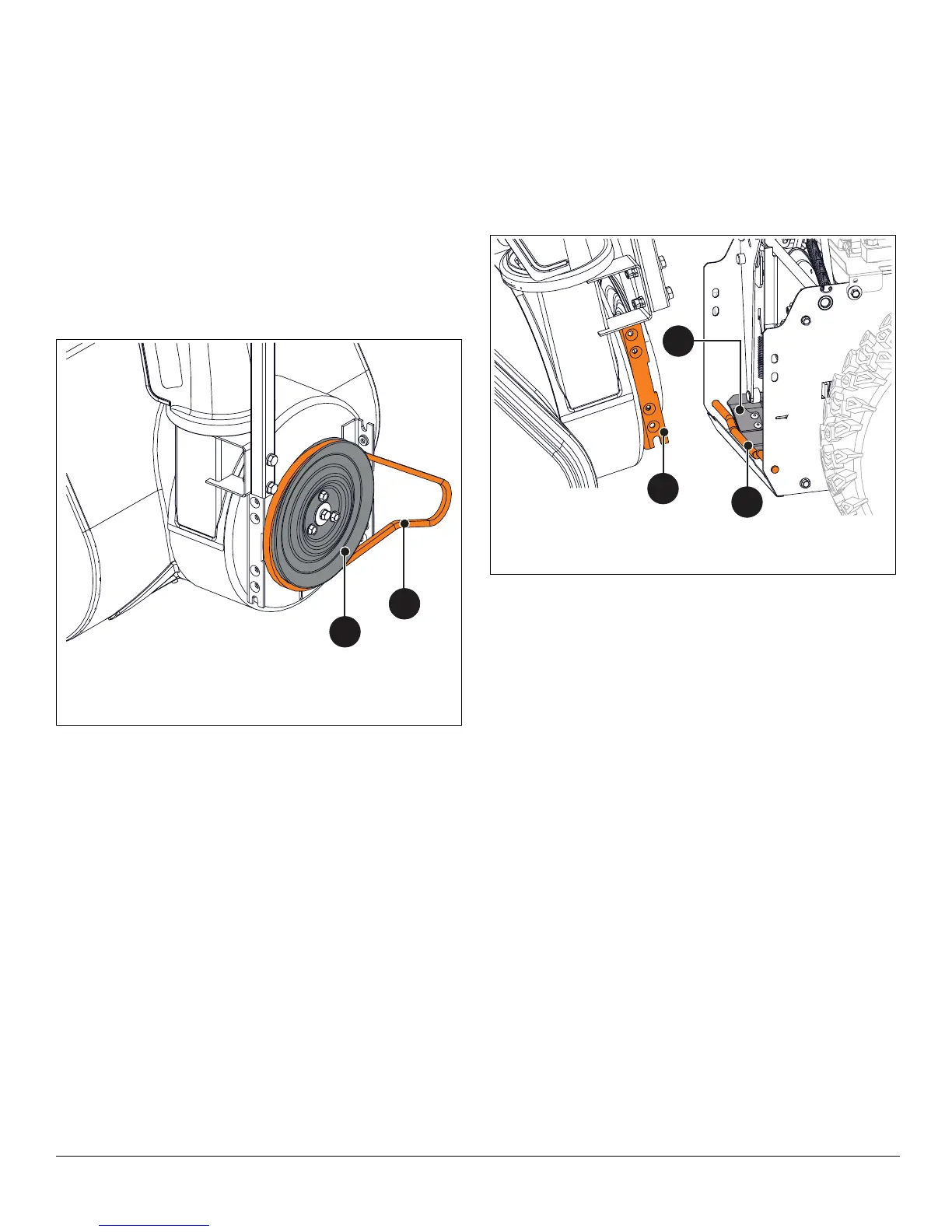
See Figure 13.
2. With assistance from a helper, engage attachment
clutch lever so attachment brake will not obstruct
attachment drive pulley in step 3.
3. Tilt auger housing rear up and lower into frame so
housing mount brackets sit on mount rod.
4. Release attachment clutch lever.
5. Align top holes in housing mount brackets with holes
in frame and reinstall, but DO NOT tighten four
tapping screws.
IMPORTANT: Unit must be on a flat, level surface during
steps 6 – 8
6. Check tire pressure and adjust if necessary. Refer to
Operator’s Manual for specification.
7. Loosen skid shoe hardware and adjust skid shoes.
Refer to Operator’s Manual for adjustment procedure.
8. Torque tapping screws installed in step 5 to
22.8 – 34.1 N•m (16.8 – 25.2 lb-ft).
See Figure 14.
9. Install attachment drive belt onto attachment sheave.
10. Reinstall belt finger and secure with two flat steel
washers, two locking washers and two hex bolts.
11. Check belt finger clearance:
• Engage attachment clutch lever and make sure belt
finger located opposite belt idler is less than 3.2 mm
(1/8") from belt, but not touching the belt.
• If needed, adjust clearance by loosening hex bolts,
repositioning belt finger, and tighten bolts.
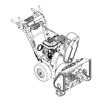
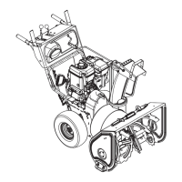
Figure 12
1. Attachment Drive Belt
2. Attachment Drive Pulley
1
2
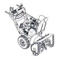
Figure 13
1. Attachment Brake
2. Mount Rod
3. Mount Bracket
1
2
3

 Loading...