EN – 29
SCRAPER BLADE REPLACEMENT
Remove Scraper Blade
NOTICE: Save all hardware for reinstallation.
1. Stop engine, remove key and wait for all moving parts
to stop and for hot parts to cool.
2. Disconnect spark plug wire from engine.
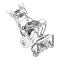
3. Slowly tip unit back so it rests on handlebars.
See Figure 49.
4. Remove hardware securing scraper blade to auger
housing and remove scraper blade.
Install Scraper Blade
1. Position scraper blade inside auger housing and align
with holes in housing.
2. Insert five flat head square neck bolts through scraper
blade and auger housing from inside housing. Secure
with top locking flange nuts.
3. Return unit to operating position.
4. Adjust scraper blade and skid shoes. Refer to
Operator’s Manual for adjustment procedures.
5. Reconnect spark plug wire.
IMPORTANT: Check all adjustments after first use.
TRACK DRIVE WHEEL REPLACEMENT
Remove Track Drive Wheel
NOTICE: Save all hardware for reinstallation.
1. Stop engine, remove key and wait for all moving parts
to stop and for hot parts to cool.
2. Disconnect spark plug wire from engine.
3. Place unit in service position. See Service Position on
page 8.
See Figure 50.
4. Remove center locking flange nuts from eye bolts on
carriage assembly to release track tension.
5. Remove snap clip retaining track drive wheel to drive
axle and remove wheel.
IMPORTANT: Be aware of key on axle ends. If key is
removed, reinstall before reinstalling wheel.
WARNING: AVOID INJURY. Before tipping unit
onto handlebars, close fuel valve and drain fuel
from tank and fuel system. See Draining Fuel
System on page 8. Make sure unit is secure and
will not fall.
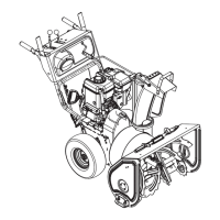
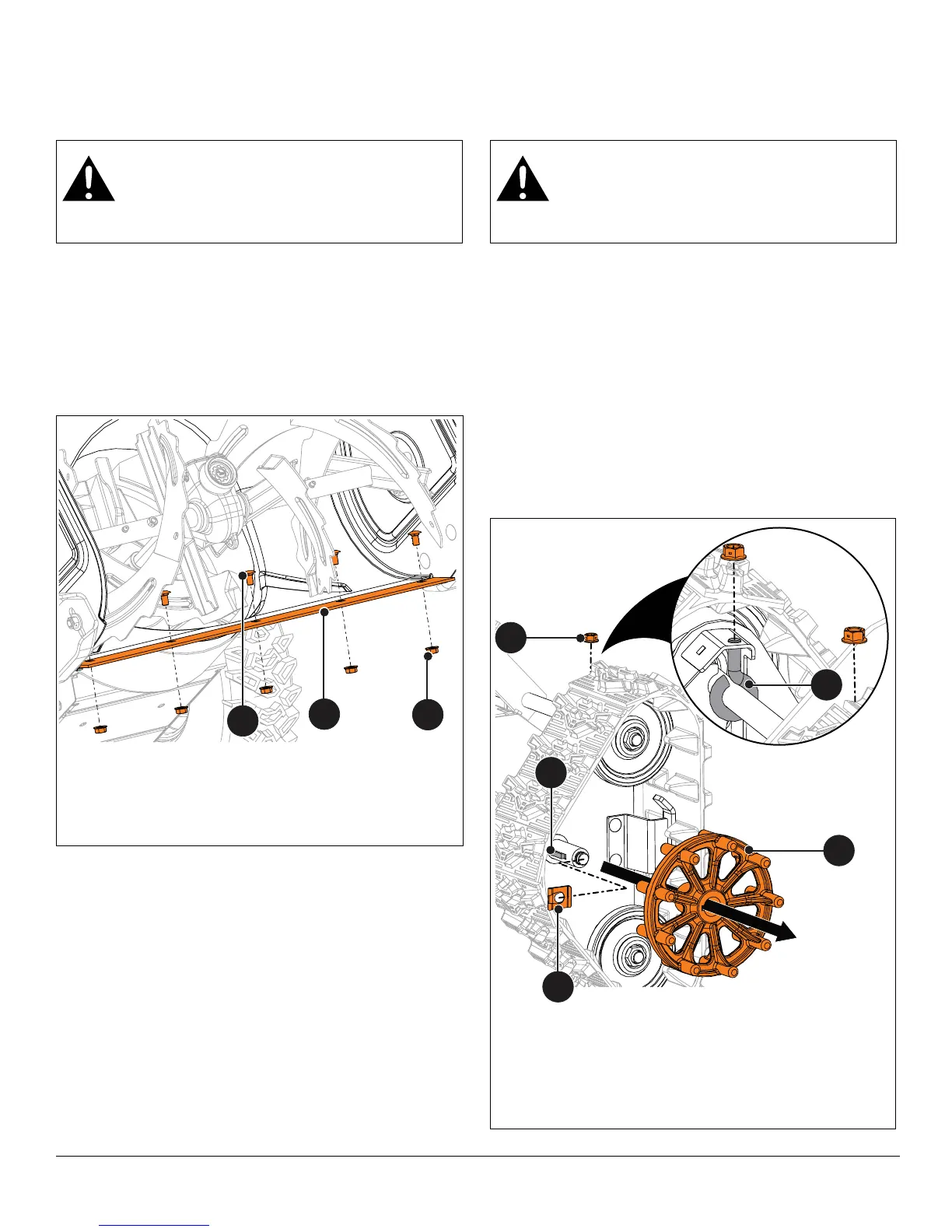
Figure 49
1. Top Locking Flange Nut
2. Scraper Blade
3. Flat Head Square Neck Bolt
12
3
WARNING: AVOID INJURY. Before placing unit
in service position, close fuel valve and drain
fuel from tank and fuel system. See Draining
Fuel System on page 8. Make sure unit is
secure and will not tip.
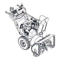
Figure 50
1. Track Drive Wheel
2. Center Locking Flange Nut
3. Eye Bolt
4. Snap Clip
5. Key
1
5
4
2
3

 Loading...