EN - 21
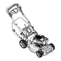
3. Model 911608: Place front of unit in
highest height of cut position. Remove
locking nuts from behind wheel plates.
Remove shoulder bolts retaining front
wheels and remove wheels.
See Figure 31.
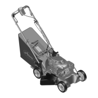
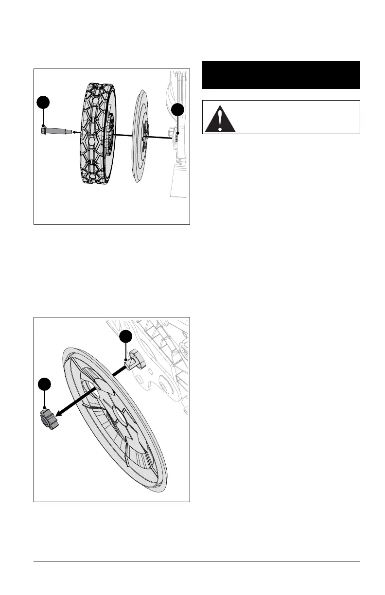
4. Remove pinion gears.
5. Clean dirt and debris from transmission
shaft ends and pinion gears. Apply anti-
seize compound to shaft end.
NOTICE: DO NOT apply grease to gear
teeth. Clean grease and debris from gear
teeth before reassembly.
3. Reinstall pinion gears.
4. Apply recommended amount of Red
Loctite® 263 (or equivalent) locking
compound to shoulder bolts.
5. Reinstall wheels and secure with
previously removed hardware.
6. Torque shoulder bolts and locking nuts to
16.3 N•m (144 in-lbs).
IMPORTANT: All references to left, right, front
or rear are given from the perspective of
operator in operator’s position, facing the
direction of forward travel.
ADJUST WHEEL DRIVE
CONTROL LEVER / REFLEX
DRIVE HANDLE
1. Model 911608 only: Mower forward
speed should increase as wheel drive
control lever is pulled closer to handle. If
unit does not accelerate smoothly, slips
under load or creeps forward when lever
is released, wheel drive control cable may
require adjustment.
2. Models 911609, 911614 only: Mower
forward speed should increase as
REFLEX drive handle is pushed down to
match operator’s pace. If unit does not
accelerate smoothly, slips under load or
creeps forward when handle is released,
wheel drive control cable may require
adjustment.
IMPORTANT: DO NOT over-adjust cable and
disable the return-to-neutral function.
Forward drive MUST stop immediately when
wheel drive control lever is released.
3. Stop engine and wait for moving parts to
stop and for hot parts to cool.
4. Clean dirt and debris from the drive
components.
IMPORTANT: Ensure extension spring is
connected to transmission bracket. See
Figures 32 and 33.
Figure 30
2
1
1. Shoulder Bolt
2. Locking Nut
1
2
1. Transmission Shaft
2. Pinion gear
Figure 31
SERVICE &
ADJUSTMENTS
CAUTION: AVOID INJURY. Read
and understand the Safety section
before proceeding.