BOILER PROTECTION DEVICES
/ 40
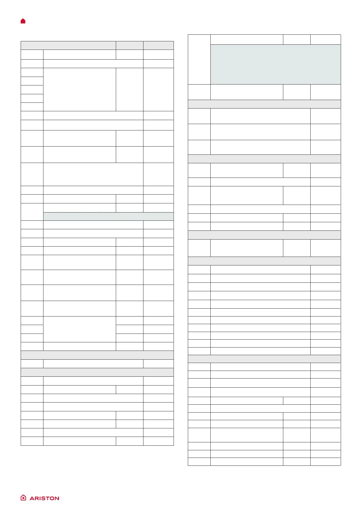
Table summarising error codes
Central Heating circuit Visibility
1 01 Overheat Reset Display
1 02 Pressure Sens Error Display
1 03
Insufcient circulation Reset Display
1 04
1 05
1 06
1 07
1 08 Insufcient water (request lling) Display
1 09 High primary circuit pressure Display
1 10
C.H. Flow temp. probe
circuit open / short circuit
Reset Display
1 12
C.H. Return temp. probe
circuit open / short circuit
Reset Display
1 14
External temperature not available
check external probe or internet
temperature
Display
1 16 Floor thermostat open Display
1 47 Pump Locked Reset Display
1 48
Pump Dryrunning Reset Display
visible with parameter 247 = 0
1 49 Pump Generic Error Display
1 51 Pump electrical error Display
1 62 Boiler parametrization fault
Warning
Error list
1 63 Boiler parametrization KO
Warning
Error list
1 64
Boiler parametrization OK -
waiting for NTCs
Warning
Error list
1 65
Boiler parametrization
missing
Warning
Error list
1 66
Boiler parametrization
allowed
Warning
Error list
1 67
Boiler parametrization
waiting for reset
Warning
Error list
1 P1
Flow check failed
Warning
Error list
1 P2
Warning
Error list
1 P3
Warning
Error list
1 P4 Filling needed
Warning
Display
D.H.W. circuit
2 05 DHW In Probe Open Circuit (SOLAR) Display
Internal P.C.B.’s
3 01 EEPROM error Display
3 03 Main P.C.B. error Reset Display
3 04 Too many (> 5) resets in 15 minutes Display
3 06 Main P.C.B. error Display
3 07 Main P.C.B. error Reset Display
3 09 Gas relais check failed Reset Display
3 13 Low Voltage Fault Display
3 15 Pump communication error
Warning
Display
3 23
PCB System error
Warning
Error list
The display shows:
“Error
Power off/on the boiler, then press reset also if this
message appears again “
Press the RESET button.
3 P9
Sched.Maintanace
Call Service
OK Display
External P.C.B.’s
4 11
Zone 1 - Room sensor circuit
open / short circuit
Display
4 12
Zone 2 - Room sensor circuit
open / short circuit
Display
4 13
Zone 3 - Room sensor circuit
open / short circuit
Display
Ignition and Detecion
5 01
No ame detected
(After 5 times with 5P6)
Reset Display
5 02 Flame detected with gas valve closed Display
5 03
Flame detected with gas
valve closed
Reset Display
5 04 Flame lift Display
5 P3 Flame cut-off Warning Error list
5 P6 Ignition Failed Warning Error list
Air Inlet / Flue gas outlet
6 12
Fan Error (speed higher or
lower than the set values)
RESET Display
Multi-zone Heating
7 01 Zone 1 send sensor defective Display
7 02 Zone 2 send sensor defective Display
7 03 Zone 3 send sensor defective Display
7 11 Zone 1 return sensor defective Display
7 12 Zone 2 return sensor defective Display
Zone 3 return sensor defective
7 22 Zone 2 overheating Display
7 23 Zone 3 overheating Display
7 50 All Heating Zones locked Display
7 P0 Pump locked Warning
7 P1 Pump error: low ow rate Warning
Combustion Control System (CCS)
8 01 Calbration Fault Error list
8 02 Calbration Tuning Fault Display
8 04 Decoupling Clip-In required Display
8 05 Calibration fault Error list
8 75 Ionization control deviation Reset Display
8 76 Calbration Fault Display
8 77 Actuators driver fault Reset Display
8 P1 Ionization control deviation Warning Display
8 P2
Offset adaptation
incomplete
Warning Display
Calibration comfort logic
8 P8 Calibration comfort logic Warning Error list
8 P9 Calibration comfort logic Warning Error list

 Loading...