55 / GB
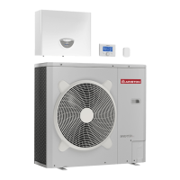
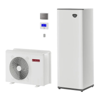
A - Flow water temperature (°C)
B - External air temperature (°C)
Restrictions of cooling operation Restrictions of heating operation
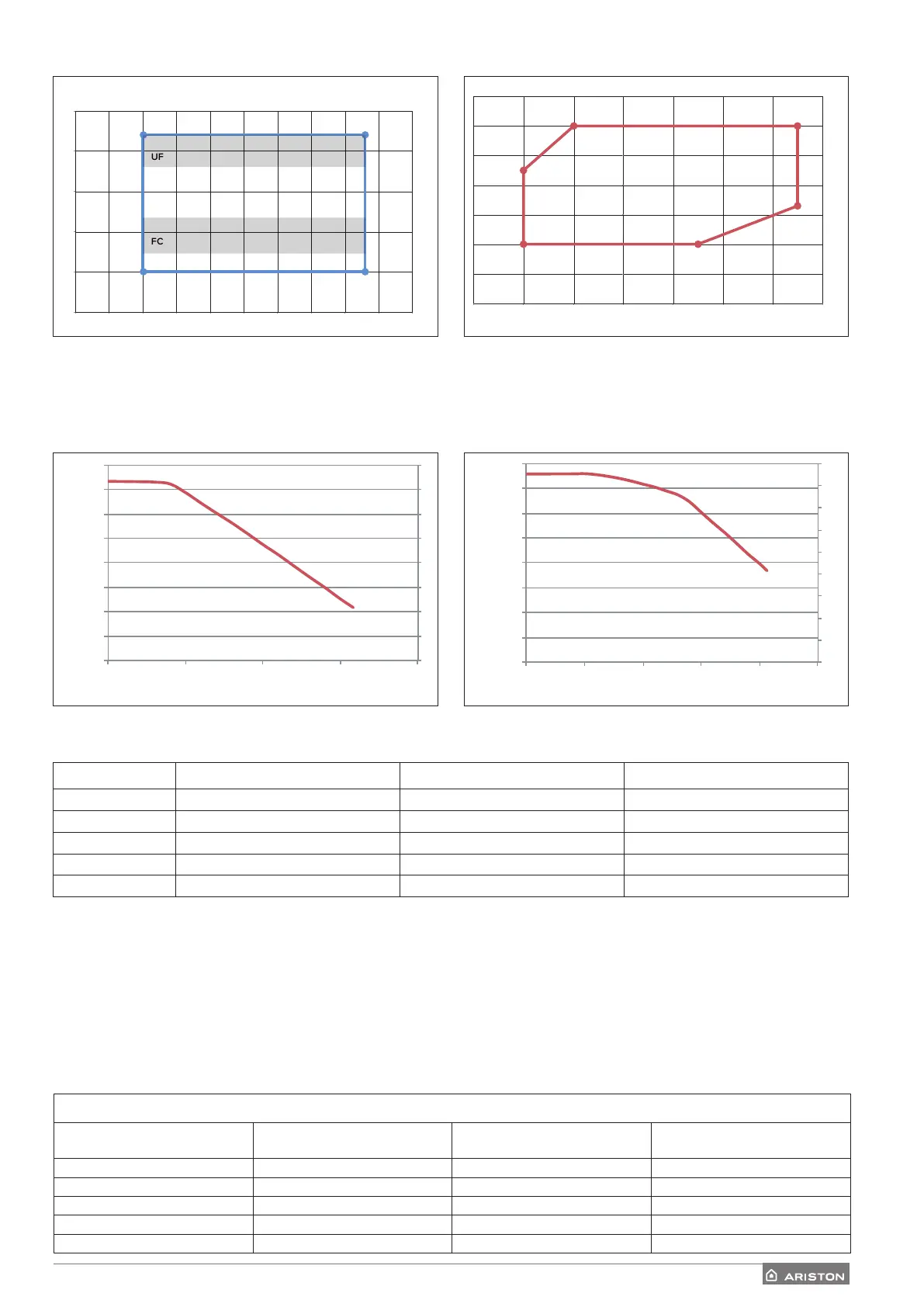
AVAILABLE PRESSURE
Pressure available for distribution on the installation.
Available pressure
The curves indicated above show the available pressure of internal units.
In order to have a correct sizing of the system, the pressure drop curve of the entire circuit (in function of the nominal ow rate)
must stay below the available pressure curve everywhere. Pressure drop values depend on the specic installation.
You can install a supplementary circulation pump if the module’s own unit is not powerful enough. For the electrical hookup, refer
to «Electrical circuit».
Warning: in case of installation of thermostatic valves on all terminals or zone valves, install a bypass to ensure the minimum
operating ow rate.
(43 ; 23)
(43 ; 5)
(10 ; 5)
(10 ; 23)
UF
0
5
10
15
20
25
0 5 10 15 20 25 30 35 40 45 50
FC
A
B
-20,45
-10,60 35,60
35,33
15,20-20,20
0
10
20
30
40
50
60
70
-30 -20 -10 0 10 20 30 40
B
A
0
100
200
300
400
500
600
700
800
0 500 1000 1500 2000
mbar
l\h
pac 3 medium WH wilo yonos 100% pwm
pac 3 big wilo yonos 100% pwm
0
100
200
300
400
500
600
700
800
0 500 1000 1500 2000 2500
mbar
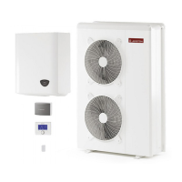
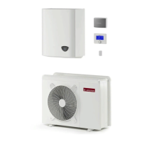
Available pressure for sizes:
: 40 S - 50 S - 70 S - 70 S-T EXT
Available pressure for sizes:
: 90 S - 90 S-T - 110 S - 110 S-T EXT
1
Example: 1B = 35 and A = 33
System Size Flowmeter OFF Threshold [l/h] Flowmeter ON Threshold [l/h] Nominal flow rate [l/h]
40 S 348 390 640
50 S 348 390 800
70 S - 70 S-T 486 540 1120
90 S - 90 S-T 630 702 1440
110 S - 110 S-T 768 852 1755
COMPRESSOR FREQUENCY TABLE
Heat Pump Frequency min [Hz] Frequency max (heat) [Hz] Frequency max (cool) [Hz]
4 kW 18 80 65
5 kW 18 100 80
7 kW 18 90 70
9 kW 18 75 57
11 kW 18 90 70
 Loading...