installation &
operating instructions
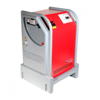
3750 Pulpress
Pressurisation unit
21
26.0 fault finding chart
section problem
1 Pump(s) run continuously
2 Pump(s) will not run
3 High pressure
4 Low pressure
5 Low water level
26.1 pump(s) run continuously
symptom/cause action
Very high leakage rate
Check system for leaks. Check for split in
vessel bag via the air valve. Check non-
return valve is not bypassing through
second pump.
Faulty electrical circuit
Check that all wiring is in place and not lose
at any connections
System pressure
setting set too high
Compare system setting pressure (System
data on display nameplate). With Fill
pressure (pi) on data plate. To reset consult
Armstrong Service Dept.
Air lock
Check the pumps for presence of air and
ensure that the air is removed.
26.2 pump(s) will not run
symptom/cause action
Pump(s) tripped
Check miniature
Circuit breakers and Reset if necessary.
Faulty electrical circuit
Check that all wiring is in place and not
loose at any connections
Pump(s) burnt-out
seized
Repair or replace pumps.
Mode of operation
Check if the unit is enabled for bas control or
local control.
26.3 high pressure
symptom/cause action
Incorrect capacity of
vessel or larger system
than originally specified
Check system and vessel capacity by recal-
culating sizes.
Failure to maintain air
charge
Isolate and drain the vessel. Adjust the
air charge to match the fill pressure of the
system
26.4 low pressure
symptom/ cause action
Pump(s) tripped
Check miniature circuit breakers and reset
if necessary
Pump(s) burnt-out
seized
Repair or replace pumps
System leakage rate
very high
Check system for leaks. Check for split
vessel bag via the air valve. Check non-
return valve is not bypassing through
second pump
symptom/ cause action
No water in tank or
spasmodic water
supply
Ensure that incoming water supply is
functioning i.e. check isolating valve is open,
ballcock operates and water is clean
Delivery/suction
isolating valve closed
Open valves.
Suction strainer(s)
obstructed
Repair or replace strainers
Air lock
Check the pumps for presence of air and
ensure that the air is removed.
26.5 low water level
break tank
symptom/cause action
No water in break tank
or intermittent water
supply
Ensure that incoming water supply is func-
tioning (i.e. check isolating valve is open,
ballcock operates and water is clean).
Incoming water pres-
sure is not sucient
Increase the water pressure,
Consult Armstrong Service Dept.
alarm
symptom/cause action
Faulty electrical circuit
Check that all wiring is in place and not
loose at any connections
Broken or damaged
float switch
Replacement float switch required
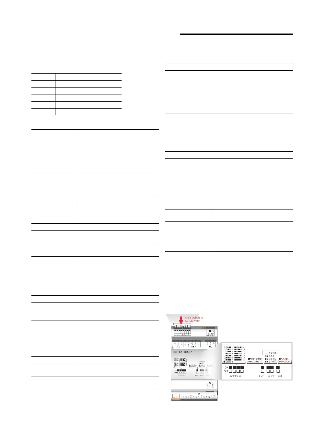
26.6 offline alarm _ cpcoe
symptom/cause action
c.pcoe loses connec-
tion to c.pco. mini
Check the wiring. All the dip switches
on c.pcoe under J10 port must be o
except the one highlighted in the below
picture
i.e. Address=1. For a twin-system unit
cpcoe-1 needs to have Address=1 and
cpcoe-2 needs to have Address=2.
 Loading...