installation &
operating instructions
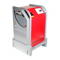
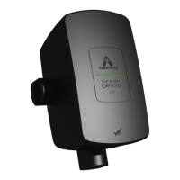
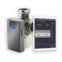
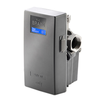
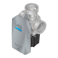
3750 Pulpress
Pressurisation unit
4
1.0 ce conformities
lvd bs en 61010-1
Low voltage switchgear bs en 61439-1
Safety of machinery bs en iso 12100
Safety of machinery bs en 60204-1
Electromagnetic compatibility
Harmonic emissions bs en 61000-3-2
Electrostatic discharge bs en 61000-4-2
Radiated rf immunity bs en 61000-4-3
Fast transient bursts bs en 61000-4-4
Voltage surges bs en 61000-4-5
Conducted rf immunity bs en 61000-4-6
Voltage dips bs en 61000-4-11
Generic immunity bs en 61000-6-1
Generic immunity bs en 61000-6-2
Generic emissions bs en 61000-6-3
Generic emissions bs en 61000-6-4
Safety of stationary circulation bs en 60335-2-51
pumps for heating and service
water installation.
2.0 preface
1 The 3750 Pulpress pressurisation unit has been designed
for ease of setting and operation.
2 All packaged pump systems are pre-wired and fully tested
prior to dispatch.
3 If ordered with system criteria, all parameter data has
been entered into the controller in accordingly. Once
on-site connections have been made, and all pre-checks
carried out, the system is ready for commissioning.
4 During commissioning if system conditions are found to
vary from those set out in the design criteria, the parame-
ters can be easily changed.
3.0 introduction
1 This installation and operation manual contains specific
information regarding safe installation, operation and
maintenance of the
3750 Pulpress pressurisation unit.
These instructions must be read and understood by
anyone responsible for the installation and maintenance
of this equipment.
2 Prior to connect the unit to the power supply, it is
essential that all Pre-commissioning procedures are
carried out in full.
3 Operators and installers must familiarise themselves with
the operation and controls of the equipment.
4.0 warning symbols
Safety instruction where an electrical hazard is
involved.
Safety instruction where non-compliance would
aect safety.
Safety instruction relating to safe operation of the
equipment. (Attention)
5.0 safety instruction
1 This equipment has been designed for the pressurisation
of sealed heating, chilled water and closed condenser
water systems to the operating conditions shown.
2 This equipment should not be installed until operation and
maintenance instructions has been studied and under-
stood by the person(s) responsible.
3 Handling, transportation and installation of this equip-
ment shall only be undertaken with the use of appropriate
lifting gear.
4 The set shall not be used for any purpose other than that
for which it was designed and sized.
5 The set shall not be operated with the cover removed and
the cover interlocked isolator overridden.
note
During normal operation, the pumps will only gen-
erate pressures sucient to satisfy system demand.
However, abnormal running conditions may cause
closed valve pressures to be experienced.
6.0 range definition
system(s) pump(s) pressure range
1 1 Low
Med
High
2 Low
Med
High
2 1 Low
Med
High
2 Low
Med
High
Low Pressure = 0.5-2.7 bar
Med Pressure =
0.5-5.5 bar
High Pressure =
0.5-8.0 bar