installation &
operating instructions
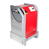
3750 Pulpress
Pressurisation unit
7
6 Never dry run the pump.
7 For wall mounting, wall structure will need to be deter-
mined to select appropriate fasteners. Ensure there are no
pipes or electrical cables running behind where the wall
bracket is to be secured.
14.2 electrical
1 The power supply required is 240 volt ±10%, 1 phase, 50
Hz or 60 Hz to suit motors fitted.
2 The incoming supply should be connected to the door
interlocked isolator from a local
10 amp switched fused
spur and if possible an elcb unit.
3 All incoming cable glands should be
ip54 rated as
a minimum.
4 Wire the set control systems (see enclosed wiring
diagram) from the volt free terminals to the boiler
control system.
5 Boiler/chiller interlock provided via normally open volt
free contact.
6 The set must be earthed.
attention
It is the user’s or certified electrician’s responsibility
to ensure correct earthling and protection in accord-
ance with applicable national and local requirements
and standards.
important safety information
1 The voltage on the 3750 Pulpress unit is dangerous when
it is connected to the mains. Incorrect installation of the
set may lead to material damage or serious injury or
death. Consequently, you must comply with the instruc-
tions in this manual as well as the local rules and
safety regulations.
2 Touching the electrical parts may be fatal, even after the
mains supply has been disconnected, wait at
least 4 minutes.
3 The installation must be fused and isolated correctly.
4 Covers and cable glands must be fitted.
15.0 safety regulations
1 The 3750 Pulpress unit must be disconnected from the
mains if repair work is to be carried out. Check the mains
supply has been disconnected and the necessary time has
passed (4 minutes).
2 The correct protective earthing of the equipment must be
established, the user must be protected against supply
voltage, and the set must be protected against overload in
accordance with applicable national and local regulations.
3
RCDs (elcb relays), multiple protective earthing or earth-
ing can be used as extra protection, provided that local
safety regulations are complied with.
16.0 commissioning
1 Fill the system with water via the quick fill connector. It
is essential that all air in the system is allowed to escape
freely through automatic air vents and radiator bleeds,
failure to remove air could result in a system malfunction.
2 Turn on the water supply feeding the
3750 Pulpress unit
and fill the break tank.
3 Check pumps are primed by loosening cap on the delivery
side of the pump–let water escape until no air is present,
put back caps and pressurize to the ambient temperature
set pressure. Never dry run the pumps.
4 With cover interlock isolating switch in the o position
switch on the power supply to the unit.
17.0 operation
Turn the main isolating switch to the On position. The system
pressure will be displayed on the digital readout. The unit will
automatically maintain pressure in the system as set out in
the design criteria and will only operate when the pressure
falls between the systems fill pressure and the pump cut-in
pressure. For twin system unit, both the system pressures
will be displayed on the digital readout. The unit will operate
on both the systems simultaneously.
18.0 heating system
Start the boiler(s). The water from the system will flow into
the vessel(s) and the system pressure will rise slowly and
settle at a pressure below the maximum pressure shown on
the nameplate. If the boiler safety valve lifts, check the valve
setting and the system details, against the ordering specifi-
cation for the
3750 Pressurisation unit.
19.0 chiller systems
When the chiller(s) are started the water contracts as it cools
and the expansion vessels will pass water to the system to
bring the pressure up to the ambient temperature setting
pressure. When the chiller is switched o the expanding wa-
ter will pass into the expansion vessel, the pressure will rise
and settle at a pressure below the maximum pressure shown
on the nameplate.