installation &
operating instructions
Design Envelope 4300 & 4380
Vertical In-line Pumping Unit
10
2.1.3 additional motor protection
With the exception of supply fuses / MCB’s to protect
the installation (for over-current and short-circuit
protection), no additional overload or over-tempera-
ture protection is required (i.e. thermal overloads).
Protection features include:
• Mains phase loss
• Over voltage
• Under voltage
• Electronic thermal motor protection
• Short circuit on motor terminals
• Ground fault on motor terminals
• Over temperature
2.1.4 motor thermal protection and derating
The Design Envelope motors are thermally protected in case
limits are exceeded (140°c), another protection is provided
thought the drive.
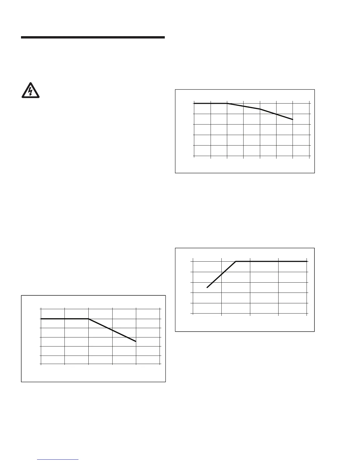
2.1.4.1 derating for ambient temperature
The ambient temperature (tamax) is the maximum tempera-
ture allowed.
If the motor is operated at temperatures above 104°f (40°c),
a derating of the continuous output current is necessary.
2.1.4.2 derating for air pressure
Below 1000 m altitude no derating is necessary. Above 1000
m the ambient temperature (ta) or max. rated output cur-
rent (in) must be de-rated in accordance with the following
diagram.
See the below diagram for derating of output current versus
altitude at ta = Max. 104°f (40°c)
2.1.4.3 derating for running at low speed
When a centrifugal pump or a fan is controlled by a 4300 &
4380 Motor, it is not necessary to reduce the output at low
speed because the load characteristic of the centrifugal pumps/
fans, automatically ensures the necessary reduction.
The 4300 & 4380 iECM motors running constant load torque
applications continuously at low speed must be de-rated (see
diagram) or an independent fan must be used.
In the iECM all control terminals are supplied from or in con-
nection with extra low voltage (pelv).
The components that make up the electrical isolation, as de-
scribed below, also comply with the requirements concerning
higher isolation and the relevant test as described in en 50178.
The galvanic isolation can be shown in three locations (see
drawing below),namely:
1 Power supply (smps) including signal isolation of VDCbus,
indicating the intermediate voltage.
2 Gate drive that runs the IGBTs (opto couplers)
3 DCbus Voltage transducer (opto couplers)
0
20
40
60
80
100
120
20 30 40 50 60 70
outputcurrent
tambient[°c]
deratingforabmienttemperature
0
20
40
60
80
100
0500 1000 1500 2000 2500 3000 3500
ratedtorque [%]
altitude[m]
deratingforair pressure
0
20
40
60
80
100
010002000300
000
ratedtorque [%]
ratedspeed[rpm]
deratingforrunningatlowspeep