installation &
operating instructions
Design Envelope 4300 & 4380
Vertical In-line Pumping Unit
27
a maximum flow setting. This will prevent over-pumping and
save energy costs. Over-pumping is common in hvac systems
as pumps are typically oversized for the application. Pump
controls can only control the flow to a minimum speed; thus a
dry-contact relay is supplies which will close when maximum
flow is reached, which can be used for an alarm or other device.
0
200
400
600
800
1000
1200
target curve
Maximum Flow Setting
5.7 quadratic curve control with minimum
& maximum flow protection
This control mode combines the control logic of 5.5 & 5.6
which takes the values of the quadratic control curve and
protection for both the maximum & minimum flow limits. Pump
controls can only control the flow to the motor limit or maxi-
mum / minimum speed limits of the unit, thus a dry-contact
relay is supplies which will close when either the minimum or
maximum flow is reached, which can be used for an alarm or
other device.
0
0
20 40 60 80 100
200
400
600
800
1000
1200
120 140 160 180
target curve
Minimum & Maximum
Flow Settings
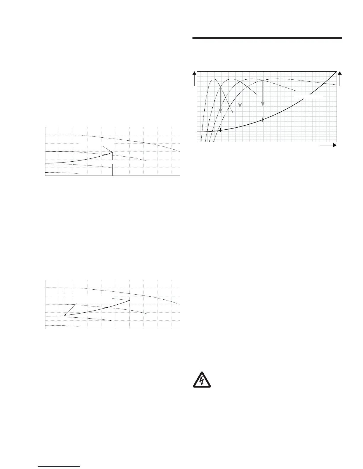
5.8 parallel sensorless pump control (pspc)
This configuration maps the system quadratic control curve
into the pspc controller where the controller intelligence
ensures the system flow requirements are met, while stag-
ing the pumps on and o to maintain optimum pump energy
usage. This is accomplished by operating the pumping units
at the best pumping eciency level for the required flow. This
controller is available for all Design Envelope equipment to a
total quantity of 6 units.
flow
1-pump
1p e 2p e 3p e 4p e
2-pumps
3-pumps
4-pumps
pspc control curve
5.9 2*100% capacity split units
When duty / standby is specified, enter the total system flow
into ACE Online or ADEPT, then select 2*100% unit split for
a superior customer value. The 100% flow redundancy is still
in place plus the onboard pspc will engage the second unit in
parallel operation should it predict lower operating costs.
If second side power is locked out, the operating pump will
operate alone on the control curve to 100% design flow.
6.0 maintenance
6.1 general care
Vertical In-Line pumps are built to operate without periodic
maintenance, other than motor lubrication on larger units. A
systematic inspection made at regular intervals, will ensure
years of trouble-free operation, giving special attention to the
following:
• Keep unit clean
• Provide the motor with correctly sized overload protection.
Keep moisture, refuse, dust or other loose particles away
from the pump and ventilating openings of the motor.
• Avoid operating the unit in overheated surroundings (Above
100°f/40°c).
warning
Whenever any service work is to be performed on
a pumping unit, disconnect the power source to
the driver, lock it o and tag with the reason. Any
possibility of the unit starting while being serviced must be
eliminated. If mechanical seal environmental accessories are
installed, ensure water is flowing through the sight flow
indicator and that filter cartridges are replaced as recommend-
ed. (See Armstrong files 43.85 and 43.86 for seal environ-
mental instructions).