installation &
operating instructions
Design Envelope 4300 & 4380
Vertical In-line Pumping Unit
14
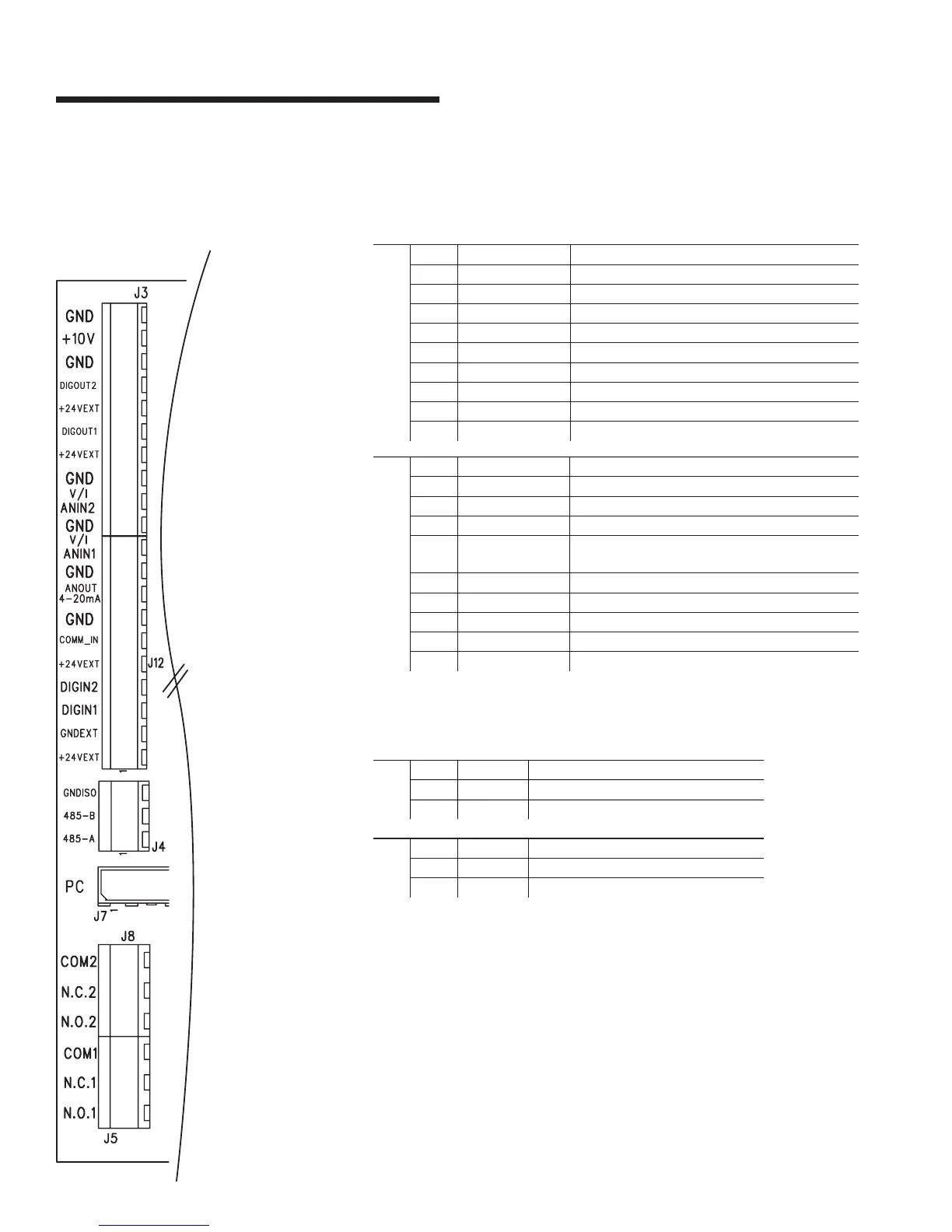
2.3.4 control terminal wiring
fig 2.3.3 Motor Control Board
2.3.5 digital & analogue input/output
J3 & J12 for Input Output
j3
pin1 gnd
gnd of the control
pin2 +10v
Voltage reference for potentiometer
pin3 gnd
gnd of the control
pin4 digout2
Digital output 2 - open collector (max 24Vdc)
pin5 +24v
ext
gnd of the control
pin6 digout1
Digital output 1 - open collector (max 24Vdc)
pin7 +24v
ext
Auxiliary power supply +24V 200mA
pin8 gnd
gnd of the control
pin9 anin2 v/i
Analog input 2 0 ÷ 10v / 0:20mA programmable
pin10 gnd
gnd of the control
j12
pin11 anin1 v/i
Analog input 1 0 ÷ 10v / 0:20 programmable
pin12 gnd
gnd of the control
pin13 anout 4-20ma
Analog output 4-20mA (500Ω
typ
)
pin14 gnd
gnd of the control
pin15 comm_in
Pull to gnd for npn input, pull to +24v for pnp
input
pin16 +24v
ext
Auxiliary power supply +24V 200mA
pin17 digin2
Digital input 2
pin18 digin1
Digital input 1 for run/stop
pin19 gnd
ext
gnd for +24v
ext
pin20 +24v
ext
Auxiliary power supply +24V 200mA
2.3.6 relay output
J5 & J8 for Relay output
j8
pin1 n.o. 2 Relay n.o.
pin2 n.c.2 Relay n.c.
pin3 com2 Relay 2A 250Vac
j5
pin1 n.o. 1 Relay n.o.
pin2 n.c. 1 Relay n.c.
pin3 com 1 Relay 2A 250Vac
2.3.7 supply voltage
The supply voltage details can be found on the 4300 & 4380 nameplate.
Please ensure that the unit is suitable for the electrical supply on which it is to
be used. The mains supply for Design Envelope pumps is as follows:
1 × 200-230v ± 10%,
3 × 200-230v ± 10%,
3 × 380-480v ± 10%,
3 × 575-600v ± 10%
Frequency - 50/60Hz