installation &
operating instructions
Design Envelope 4300 & 4380
Vertical In-line Pumping Unit
11
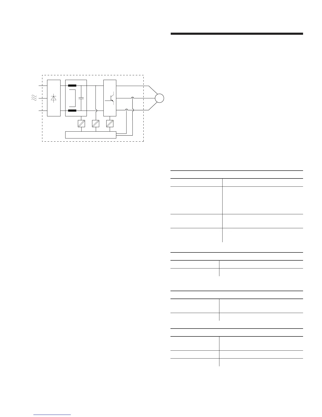
4 Current transducers (Hall Eect-Based Current Sensor).
31
4
2
M
2.1.4.3 earth leakage current
Earth leakage current is primarily caused by the capacitance
between motor phases and the motor frame. The rfi filter
contributes additional leakage current, as the filter circuit is
connected to earth through capacitors (Cy).
The size of the leakage current to the ground depends on the
following factors, in order of priority:
1 Switching pwm frequency
2 Motor grounded on site or not
The leakage current is of importance to safety during handling/
operation of the drive if (by mistake) the drive has not been
earthed.
2.1.4.4 over voltage protection
The voltage in the intermediate circuit is increased when the
motor acts as a generator. This occurs in two cases:
1 The load generates energy.
2 During deceleration (ramp-down) if the moment of inertia is
high, the load is low and the ramp-down time is too short for
the energy to be dissipated as a loss in the motor frequency
converter, the motor and the installation.
The drive turns o to protect the igbt transistors and the
intermediate circuit capacitors when a certain voltage level is
reached on DCbus.
2.1.4.5 mains supply interference/harmonics
A motor integral drive takes up a non-sinusoidal current from
mains. A non-sinusoidal current can be transformed by means
of a Fourier analysis and split up into sine wave currents with
dierent frequencies, i.e. dierent harmonic currents in with
50 Hz as the basic frequency.
Some of the harmonic currents might disturb communication
equipment connected to the same transformer or cause reso-
nance in connection with power-factor correction batteries.
To ensure low, harmonic currents, for the residential and com-
mercial environments, an optional harmonic filter is necessary.
2.2 electrical specification
Main supply (l1 l2 l3)
Supply frequency 48 - 62Hz
Supply voltage 1 × 200-230v ± 10%,
3 × 200-230v ± 10%,
3 × 380-480v ± 10%,
3 × 575-600v ± 10%
Max. imbalance of
supply voltage
± 2% of rated supply
Switching on
supply voltage
Once every 2 minutes
Output ratings
Output Current 100% Drive Rated Power continuously
Overload Capacity 150% for 60 secs
Digital inputs
Programmable
digital inputs
4
Voltage level 0-24Vdc (user selectable npn or pnp)
Pulse input
Programmable pulse
input
1
Voltage level 0:24Vdc
Max frequency 10kHz