installation &
operating instructions
Design Envelope 4300 & 4380
Vertical In-line Pumping Unit
26
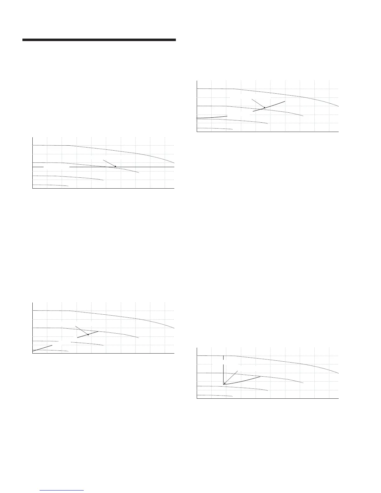
5.2 constant pressure
Design Envelope pumps can be configured to maintain a
constant pump head in a system as the demand varies. This
eectively simulates the mounting of a dierential pressure
sensor at, or near, the pump.
0
0
20 40 60 80 100
200
400
600
800
1000
1200
120 140 160 180
target curve
Constant Pressure Control Curve
5.3 linear pressure
Linear Pressure Control is where the controller is set to control
the speed according to a control ‘curve’ between max and min
flow. This type of control will change the pump speed to ensure
the pump operates on the projected linear control curve, where
the pump head varies directly with the flow. This type of control
is well known globally and is eective as far as the straight lin-
ear line will allow. For more realistic hvac control with superior
energy savings, consider the following control recommendation
5.4 Quadratic Curve Control.
0
200
400
600
800
1000
1200
target curve
Linear Pressure Control Curve
5.4 quadratic curve control
Quadratic Pressure Control is where the controller is set to
control the speed according to a control curve between max
and min flow. It is widely recognised that fitting a dierential
pressure sensor at the most remote load, across the supply
piping and return piping encompassing the valve and coil set, is
the benchmark scheme for energy eciency.
Design Envelope pumps can replicate this control without the
need for the remote sensor. As the flow required by the system
is reduced, the pump automatically reduces the head devel-
oped according to the pre-set control curve.
0
0
20 40 60 80 100
200
400
600
800
1000
1200
120 140 160 180
target curve
Quadratic Control Curve
5.5 quadratic curve control with minimum
flow protection
This configuration is designed for hvac hydronic systems
where flow sensitive equipment required a minimum flow for
equipment stability; such as a chiller that cannot tolerate flow
below a certain volume. This control will take advantage of the
5.4 Quadratic Curve Control mode, where the pump will in-
crease speed to maintain a minimum flow setting as the system
load is shutting down.
Pump controls can only control the flow to the maximum speed
or motor limit;
5.5.1 A dry-contact relay is supplies which will close when
minimum flow is reached, which can be used for an
alarm or other device.
5.5.2 When ordered, a minimum flow breach can be con-
trolled by opening a customer supplied 2-way (normally
closed) system bypass valve. The valve will be opened
and closed as system flow, which is also monitored
by the controls, registers below or above the pre-set
(adjustable) minimum flow value, using the built-in
outputs and relays in the Design Envelope pumping unit
on-board controls.
0
0
20 40 60 80 100
200
400
600
800
1000
1200
120 140 160 180
target curve
Minimum Flow Setting
5.6 quadratic curve control with maximum
flow protection
This configuration is ideal for hvac hydronic systems where
pumps are generally oversized and a flow limit is required
for system equipment stability and resulting energy savings.
This control will take advantage of the 5.4 Quadratic Curve
Control mode, where the pump will decrease speed to maintain