installation &
operating instructions
Design Envelope 4300 & 4380
Vertical In-line Pumping Unit
7
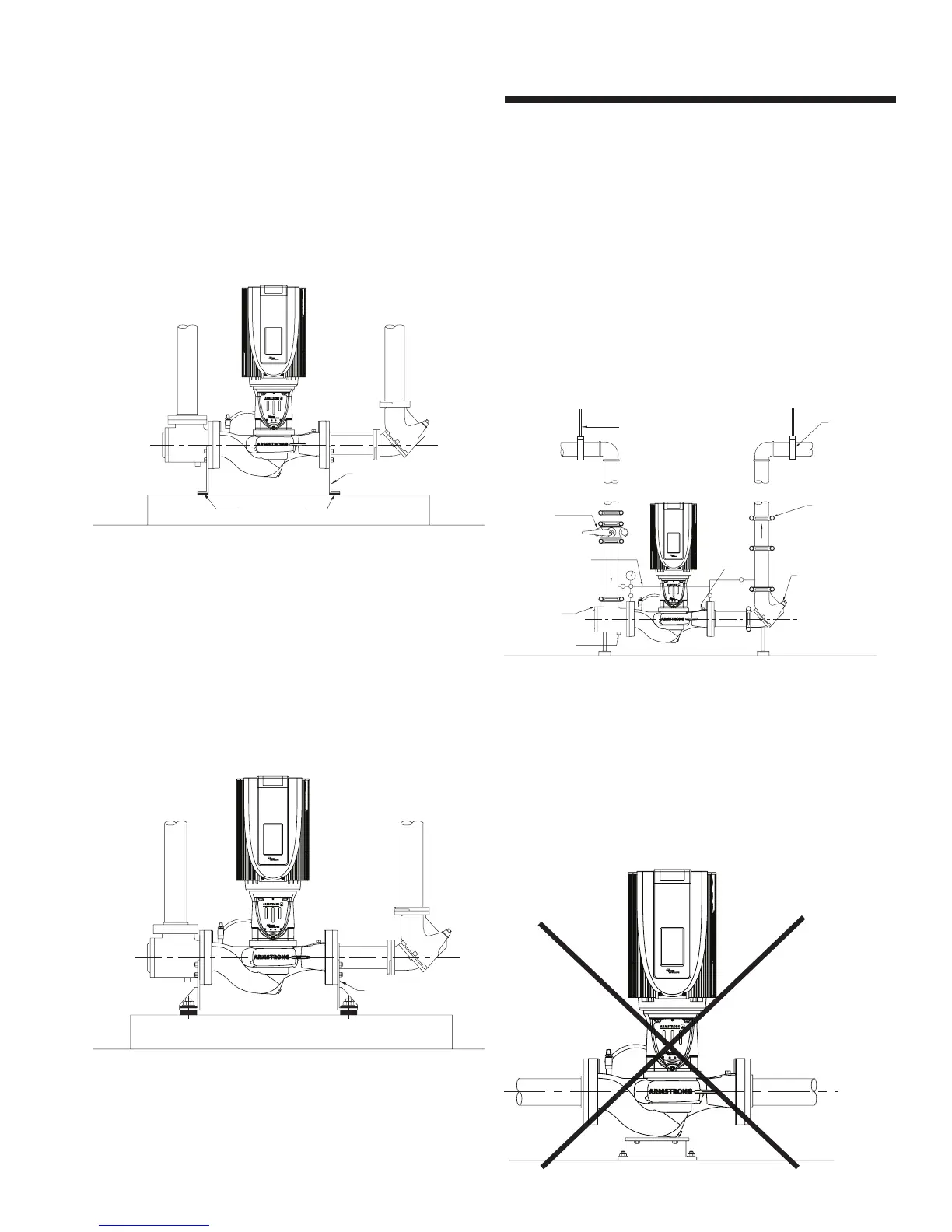
column or install a ‘wae’ isolation pad under the pump. It is
critical that piping be installed in such a manner that the pump
does not become a pipe support.
fig. 1.2.2.6
Isolation Pads
Stanchion Plates
1.2.2.7
fig. 1.2.2.7 illustrates installations with stanchion plates for
seismically active regions. Seismically rated isolation pads
or snubbers with bolts isolated from the stanchion plates are
installed to restrain the pump during a seismic event. Pipe
hangers carry the weight of the equipment as seismic com-
ponents are designed only to restrain the equipment during a
seismic event.
fig. 1.2.2.7
Seismically rated snubbers or pads and
conrete foundation
Stanchion plates
1.2.2.8
Many Vertical In-Line pumps are piped successfully into
grooved piping systems. In-line pumps are supported well by
grooved piping however flange adapter locking devices or a
welded flange at the pump should be used to prevent the pos-
sibility of pipe mounted pumps rotating in the piping. Armstrong
oers grooved suction guides with cast-in outlet flanges and
Flo-Trex valves with Armgrip™ fittings to prevent this possibility.
fig. 1.2.2.8
ain connection
System inlet
Recommended field
pressure gauge
piping arrangement
Flo-Trex valve
Pet cock
(typ.)
Pipe hanger
(typ.) See
size and type
System outlet
Flush
line
Gruvlok 7000 flex
coupling (typ.)
7700 butterfly
valve
Hangers support the weight of the
filled piping, pumps and fittings
1.2.2.9
Connecting the pump to a permanent rigid base (fig. 1.2.2.9)
is not recommended unless isolated from the piping by flexible
connectors and the base isolated from the building structure
on an inertia base. (fig. 1.2.2.9 is generally acceptable when
using plastic piping).
fig. 1.2.2.9