C
hapter
Ⅲ
G
eneral
D
escriptions
for
F
unction
B
locks
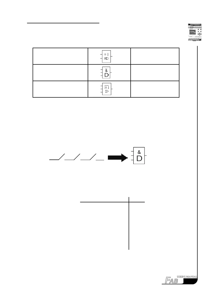
The electrical line diagram for serial
connection of a certain number of NO
contacts is shown as follows:
The symbol of AND is shown in
the follows:
17
Dual commutator contact XOR
Parallel connection of NC
contacts
NAND
Serial connection of NC con-
tacts
NOR
3.1.1 AND
This function block is called AND, because only when all of I1, I2 and I3 are in
status 1, the status of Output Q will be 1 (i.e. the output is closed).
I 1 I 2 I 3 Q
0 0 0 0
0 0 1 0
0 1 0 0
0 1 1 0
1 0 0 0
1 0 1 0
1 1 0 0
1 1 1 1
11 12 13