FAB
I
ntelligent
C
ontrollerr
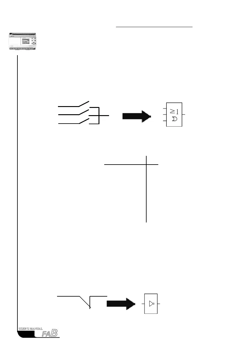
3.1.2 OR
This function block is called OR, because the status for at least one of inputs I1
or I2 or I3 is 1 (i.e. close), then output Q is 1.
Logical frame of “OR”:
0 0 0 0
0 0 1 1
0 1 0 1
0 1 1 1
1 0 0 1
1 0 1 1
1 1 0 1
1 1 1 1
3.1.3 NOT
This function block is called NOT, because the input status is 0, Output Q is 1,
and vice versa. In other words, NOT is the phase inverter for the input point.
The phase inverter is indicated in The phase inverter is called NOT the line
diagram shown as follows: in FAB, its symbol is as follows:
18
I1
11
Q
The electrical line diagram for the parallel
connection of a certain number of NO con-
tacts is shown as follows:
The symbol of OR is shown in
the follows:
I1 I2 I3 Q
Q
11
12
13
11
12
13