C
hapter
Ⅲ
G
eneral
D
escriptions
for
F
unction
B
locks
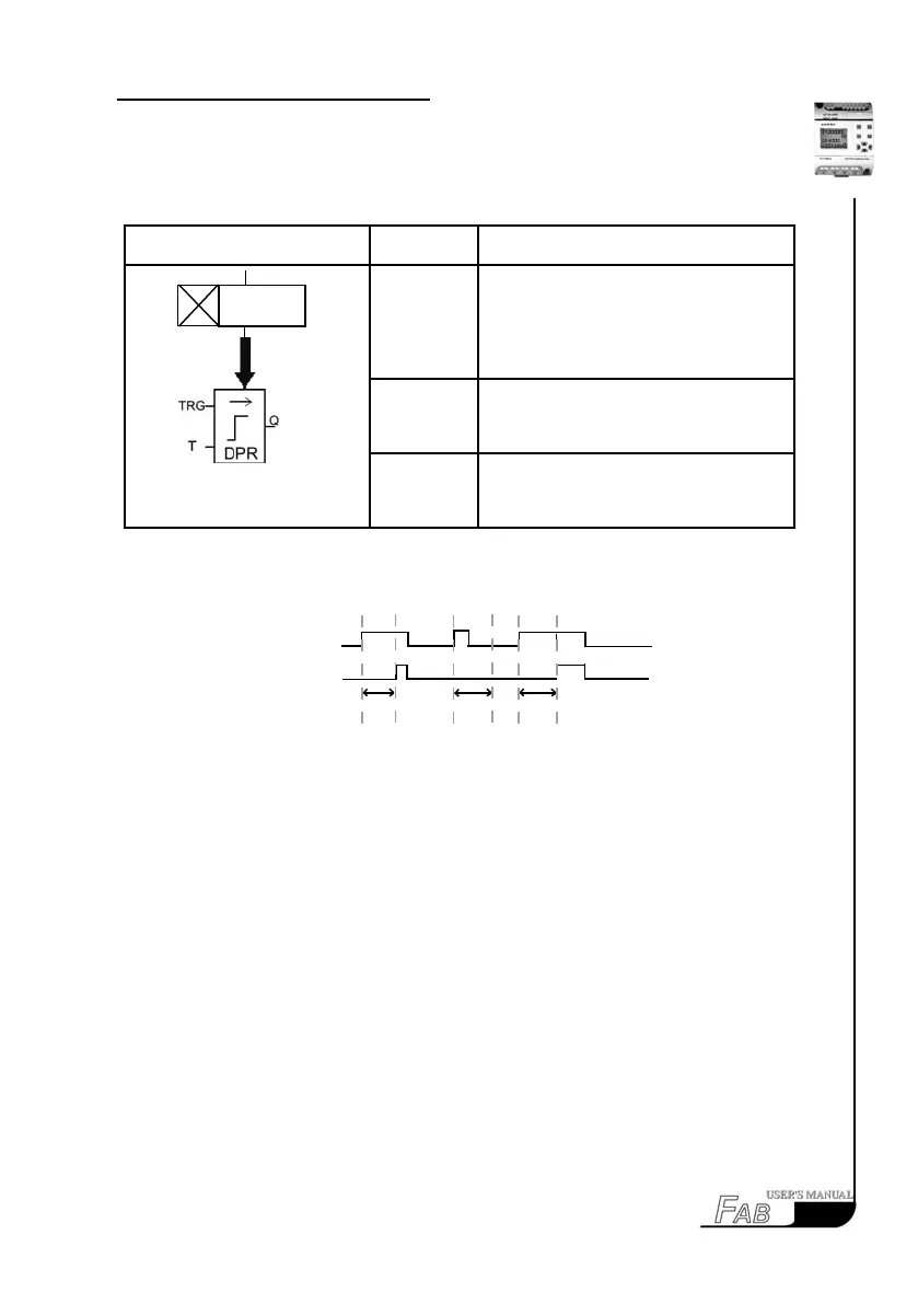
3.2.1 DPR
Line diagram/Symbol in FAB Pin Description
input TRG
After TRG is triggered, the time delay
timer starts timing. (If TRG stops trig-
gering during the timing of timer, the
timer will terminate the timing).
Parameter
T
After time T, the output is on (the output
signal transforms from 0 to 1).
Output Q
If there is still trigger signal, when time
T is over, the output will be on.
Time Sequence Frame:
Description:
1. When the status of TRG input changes from 0 to 1, the time-delay timer starts
timing. If Input TRG holds status 1 for a sufciently long time, the output will
be changed to 1 after the time T is over. There is a time delay between the input
turning ON and the output turning ON, which is why the ON time-delay is so
called.
2. When the input TRG is at Status 0, the output will reset to status 0.
3. This function is applicable to override vibrations of switches, delayed start
-up of a motor, delayed turning-on of lights, etc.
4. The assigned range for T is 0.01-99.99, and the time units can be set respec-
tively to hour (H), minute (M) and second (S). Its time accuracy can reach 0.5‰.
TRG
Q
T
T
T
23