C
hapter
Ⅳ
P
rogramming on
FAB
panel
45
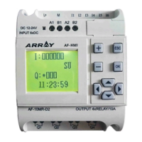
After the selection of Input/Output PIN, press OK to enter the Parameter Setting
Status, shown at the top left corner of Fig. 4.7. Firstly move the cursor to “I” po-
sition, which is at the top left corner, with , keys, and then change the to-
be connected types (I, Q, H, L, X, M, P), and press OK to conrm the changes.
Finally, increase or decrease the operands (e.g. I0, I1 and I2) for the connection
points with
and keys.
Note: The operands for different types of connection points have different
ranges: I1 ~ I6 (10-point type) or I1~IC (20-point type) for I (input) and Q1 ~
Q4 (10-point type) or Q1~Q8 (20-point type) for Q (output). Operands are not
required for H (high), L (low) and X (empty). M means intermediate relays M00
~ M126. P means two-tone code.
Fig. 4.7 Setting the parameter of function blocks
The above mentioned setting is for the basic function blocks. As for the special
ones, we need another explanation:
1. Function blocks with timing function
This kind of block includes:
DPR: Delay putting Relay CPG: Clock Pulse Generator
DDR: Delay Disconnection Relay RPR: Retentive On Relay
MPLR: Mono-pulse Relay Pulse Relay CW: Clock Switch
PLR: Pulse Relay DPR: Delay putting Relay
CPG: Clock Pulse Generator
When parameter T is set, the following frame will appear on the LCD panel
Fig. 4.8
I0
B01
B02:Time
00:Uint
00:Int
00:m