Product Drawings and References
Synergy
RF™
System Service Guide
DFU-0276-4r0_fmt_en-US Page 10 of 50
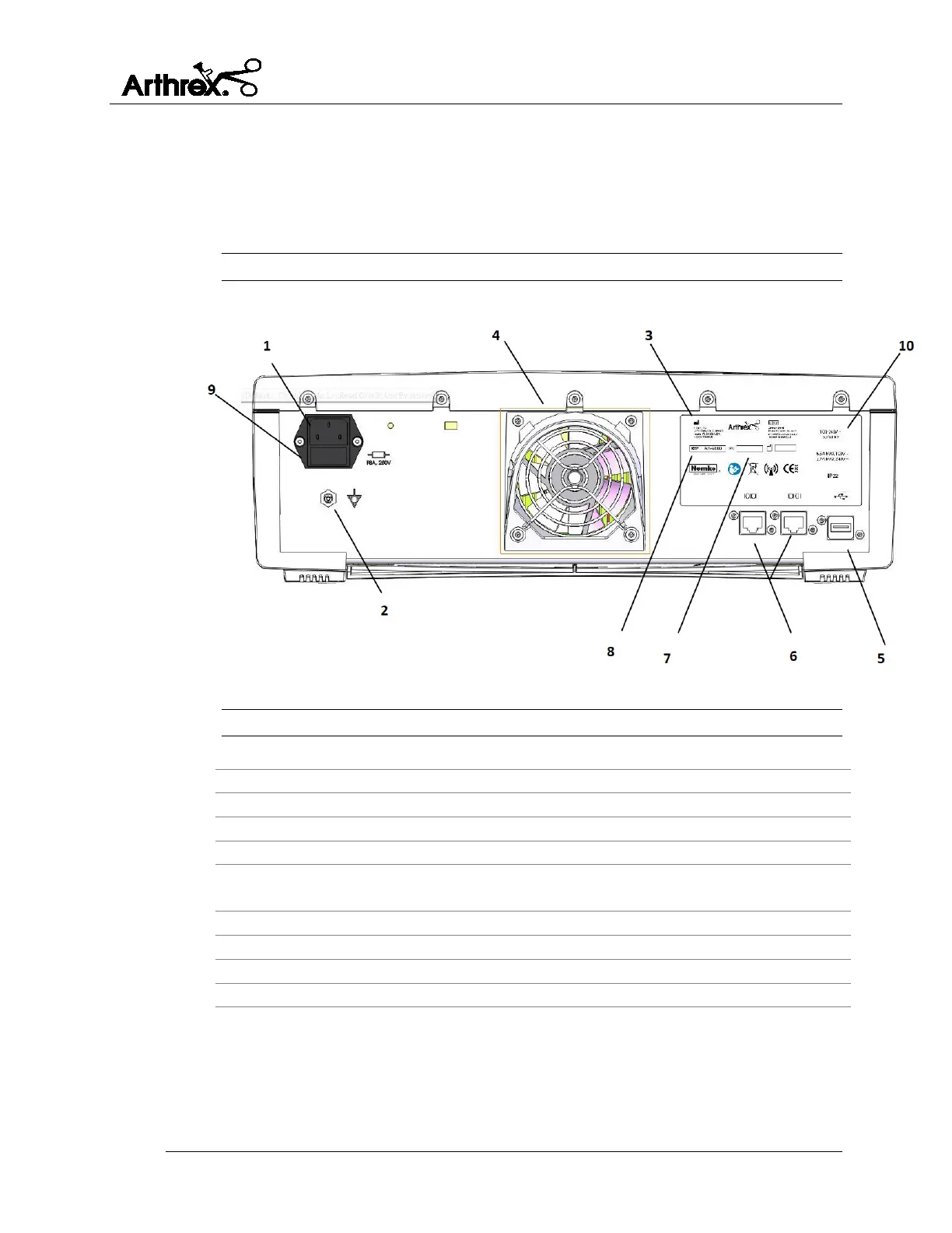
2.3.2 AR-9800 Console - Rear View
Figure 3 shows the rear panel of the console. The features and symbols are
identified in Table 3 below.
Figure 3 Rear Panel of Console
Table 3 Rear Panel Elements
Equipotential Bonding Pin with Stamped Equipotential Bonding Symbol
USB port (For use ONLY by service technicians)
Serial ports for Arthrex integration (to only be connected to IEC 60601-1
approved equipment)
Fuse holder for the Power Entry Module
 Loading...