Product Drawings and References
Synergy
RF™
System Service Guide
DFU-0276-4r0_fmt_en-US Page 15 of 50
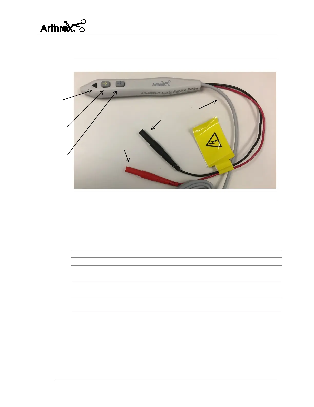
2.4.3 Apollo
RF
Service probe
Figure 7 Apollo
RF
Service probe - Description
Table 8 Apollo
RF
Service probe - Description
Change button
Each time the button is pressed, the Ablation
setting increases by 1 unit. Activation increases
ablation in a positive direction only. When the
device is at maximum power setting, the user can
return to the minimum setting by pressing the
Ablation Power Change button one more time.
Initiates ablation current.
Initiates coagulation current.
Connects to the red variable load port of
electrosurgical analyzer.
Black (-) output
connector
Connects to the black variable load port of
electrosurgical analyzer.
Connects the Service probe to the Synergy
RF
The Apollo
RF
Service probe is designed to be used by trained biomedical technicians ONLY.
The device initiates the electrical current from the Synergy
RF
console, through the service
probe, and into the electrosurgical unit (ESU) analyzer. It is intended for ESU analysis only.
It is NOT intended for use in surgical applications or to be operated by surgeons or
surgical staff.
 Loading...