Charging Rack Installation
INSTALLATION AND OPERATION MANUAL
CR3 CR5, and CR7 Charging Racks
Figure 3. Charging Rack with table adapters on the example of CR7- AAAA
2.3 Wall Mounting
Charging Rack shall not be mounted higher than 2000 mm.
Follow these steps when mounting a Charging Rack to a wall:
1. First, make an outline of how the Charging Racks are to be placed.
If several Charging Racks (or Battery Pack Chargers) are to be mounted close to each other, mount
them so that there is enough space between them to be able to disconnect the handsets (vertical
distance) and to be able to open the top cover (horizontal distance).
When you are planning the location of the modules, start to mount them in a height that makes it easy
to reach the handsets and to read the handsets’ display.
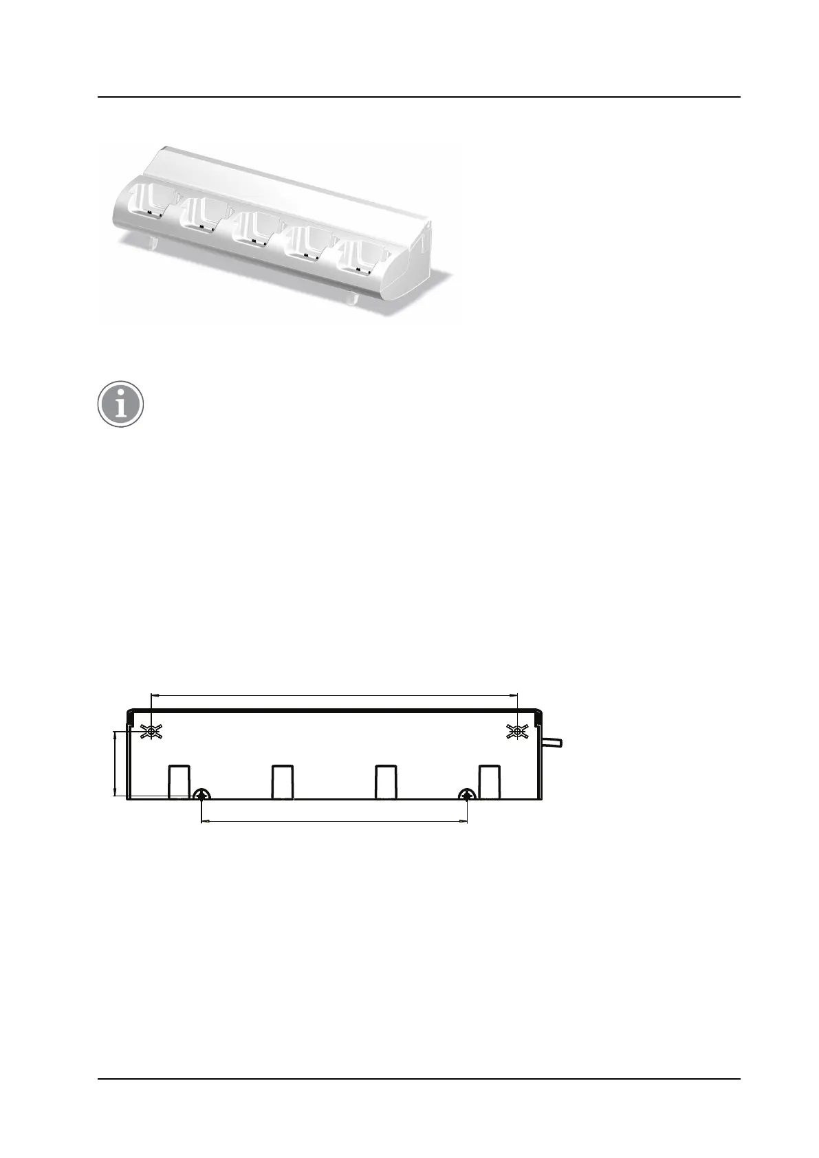
2. Measure and mark the drill holes by using the dimensions in Figure 4. Mounting dimensions in mm.
Charging Rack seen from the back, page 7.
3. Dill and fasten the Charging Rack on the wall with four screws.
Figure 4. Mounting dimensions in mm. Charging Rack seen from the back
2.4 Electrical Installation
Power Supply by Power Cord to Wall Outlet
The Charging Rack is delivered with a cord with an IEC C14 connector (male). An extension cord IEC C13 AC
connector (female, IEC60320-C13) to wall socket has to be ordered separately. It shall be connected
between the pre-installed AC connector (male) and the wall socket.
7
TD 92480EN / 30 October 2020 / Ver. L