INSTALLATION AND OPERATION MANUAL
CR3 CR5, and CR7 Charging Racks Charging Rack Installation
Table 3 Example of plug and screw dimensions
Wall material Plug length Screw diameter
Single plasterboard Thorsman TP1 3.5 – 5 mm
Double plasterboard Thorsman TP2 3.5 – 5 mm
Concrete Thorsman TP2 3.5 – 5 mm
Examples of Ways to Mount the Charging Racks
Different ways to mount the Charging Racks are shown in Figure 6. Examples of ways to mount Charging
Racks, page 9. It is possible to set up different combinations of Charging Racks and Battery Pack Chargers.
A maximum of four Advanced Charging Racks (or Battery Pack Chargers) can be serially connected to the
same LAN source.
Installation Steps for the Basic Charging Rack
The installation is done in the following way:
1. Placing on table or wall mounting, refer to 2.2 Placing on a Table, page 6.
2. Electrical installation, refer to 2.4 Electrical Installation, page 7.
Installation Steps for the Advanced Charging Rack
The installation is done in the following way:
1. Placing on table or wall mounting, refer to the 2.2 Placing on a Table, page 6.
2. Electrical installation, refer to the 2.4 Electrical Installation, page 7.
3. Communication cable connection, refer to the 2.5 Communication Cable Connection, page 12.
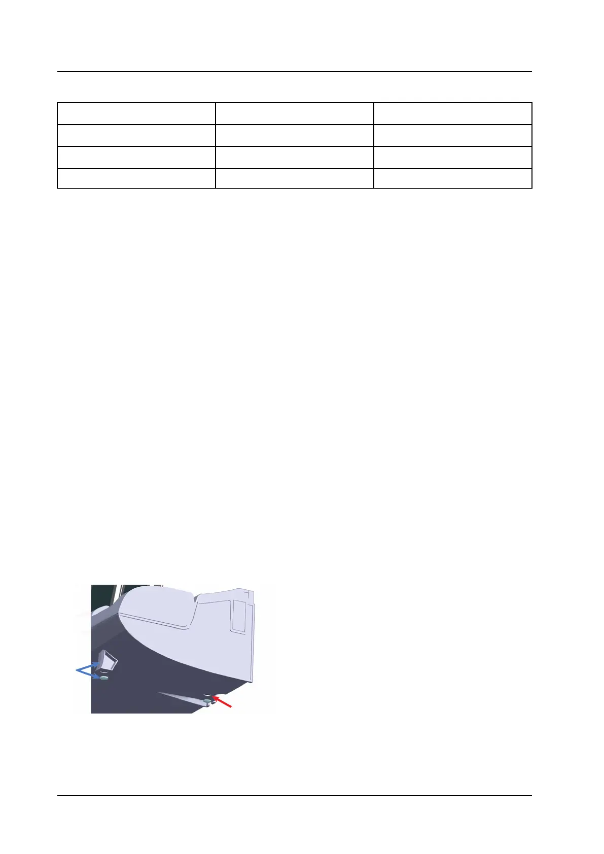
2.2 Placing on a Table
If the Charging Rack shall be placed on table, use the table adapters included in the delivery as follows:
1. Mount the two table adapters in the two outer holes in the bottom cover of the Charging Rack as
shown in Figure 2. Mounting of table adapters and rubber feet, page 6.
2. Mount the four rubber feet as shown in Figure 2. Mounting of table adapters and rubber feet, page 6.
Figure 2. Mounting of table adapters and rubber feet
Mount table
adaptor and
rubber feet
here.
Mount the rubber
feet here.
TD 92480EN / 30 October 2020 / Ver. L 6